
Novel fluorescent optical fiber sensing device

A technology of fluorescent optical fiber and sensing device, which is applied in the direction of cladding optical fiber, optical device to transmit sensing components, optical waveguide and light guide, etc., which can solve the problem of inability to achieve distributed or quasi-distributed measurement and limit fluorescent optical fiber sensing Problems such as the popularization and use of the device and the large absorption of light waves have achieved good market prospects, simple structure and low cost.

Inactive Publication Date: 2013-06-05
XIAN JINHE OPTICAL TECH
View PDF0 Cites 3 Cited by
  • Summary
  • Abstract
  • Description
  • Claims
  • Application Information

AI Technical Summary

Problems solved by technology

[0002] The existing fluorescent optical fiber temperature sensing device can only measure at a single point, and cannot achieve distributed or quasi-distributed measurement. The main reason is that when the core of the fluorescent optical fiber is doped with active fluorescent substances, the fluorescent The light wave transmitted in the core absorbs a lot, which results in a short transmission distance of both the incident light wave and the fluorescent light wave with the temperature signal, so it can only be used for single-point measurement
Limits the promotion and use of fluorescent fiber optic sensing devices in quasi-distributed or distributed monitoring

Method used


Image

  • Novel fluorescent optical fiber sensing device
  • Novel fluorescent optical fiber sensing device
  • Novel fluorescent optical fiber sensing device

Examples


Embodiment 1

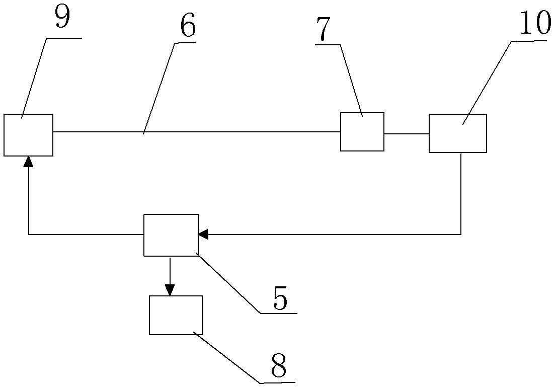
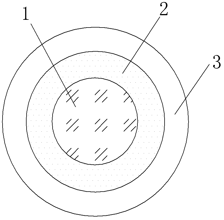
[0023] like figure 1 , figure 2 and image 3 A novel fluorescent optical fiber sensing device shown includes a fluorescent optical fiber 6, a light source module 9, a photodetector module 10 and a control processing module 5. The light source module 9 is connected to one end of the fluorescent optical fiber 6 through an optical fiber, and the fluorescent optical fiber The other end of 6 is connected to the photodetector module 10 through an optical fiber, and an optical filter 7 is arranged on the optical fiber between the fluorescent optical fiber 6 and the photodetector module 10, and the control processing module 5 is connected with the light source module 9 and the photodetector module respectively. The control module 10 is connected to the control processing module 5 with a display module 8; the fluorescent optical fiber 6 includes a core 1 and a cladding 2, the core 1 is inactive dopant, and the cladding 2 Doped with active fluorescent material, the refractive index o...

Embodiment 2

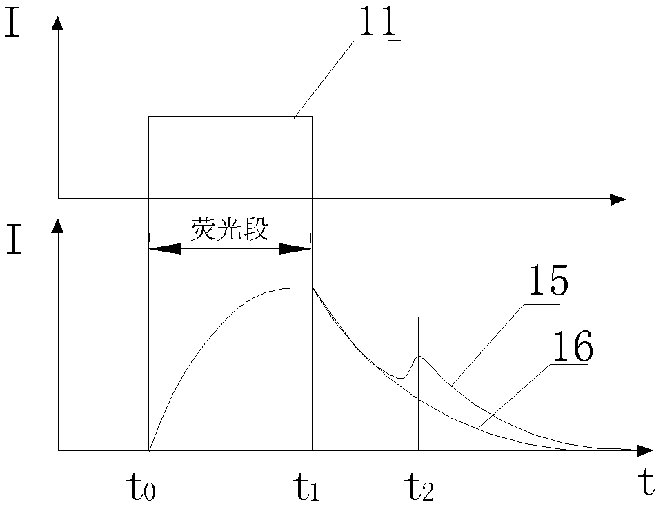
[0032] like Figure 4 As shown, in this embodiment, the difference from Embodiment 1 is that in the cladding 2, the radial distance from the interface between the core 1 and the cladding 2 to the interface between the core 1 and the cladding 2 is not more than 5 The undoped cladding region 4 is not doped with active fluorescent material in the micrometer region. In this way, only when the fluorescent optical fiber 6 is bent, slightly bent, or deformed, the incident light emitted by the light source module 9 and entering the fluorescent optical fiber 6 will be partially coupled into the cladding 2 and excite fluorescence, controlling The processing unit 5 can calculate the change position of the physical quantity to be measured according to the time difference between the time when the light source module 9 sends out the light signal and the fluorescence signal received by the light detection module 10, and calculate the change of the physical quantity to be measured according ...


PUM


Abstract

The invention discloses a novel fluorescent optical fiber sensing device which comprises a fluorescent optical fiber, a light source module, an optical probing device module and a control processing module. The light source module is connected with one end of the fluorescent optical fiber and the other end of the fluorescent optical fiber is connected with the optical probing module. An optical filter is arranged on the fiber between the fluorescent fiber and the light probing device module. The control processing module is connected with the light source module and the light probing device module. The control processing module is connected with a displaying module. The fluorescent fiber comprises a fiber core and a covering layer. A fluorescent material is organic dye or a material containing neodymium ions, erbium ions , ytterbium ions, praseodymium ions, , thulium ions, europium ion or holmium ions. Incoming light waves and fluorescent light waves with sensing information can be transmitted in a long distance on the fiber core with the novel fluorescent optical fiber sensing device so that an end portion of the fluorescent optical fiber can obtain fluorescent light waves through a light probing device and demodulate to generate variation of to-be-detected physical quantity so that the aim of distribution type or quasi distribution type monitoring and sensing is achieved.

Description

technical field [0001] The invention relates to an optical fiber sensing device, in particular to a novel fluorescent optical fiber sensing device. Background technique [0002] The existing fluorescent optical fiber temperature sensing device can only measure at a single point, and cannot achieve distributed or quasi-distributed measurement. The main reason is that when the core of the fluorescent optical fiber is doped with active fluorescent substances, the fluorescent The light wave transmitted in the core absorbs a lot, resulting in a short transmission distance of both the incident light wave and the fluorescent light wave with the temperature signal, so it can only be used for single-point measurement. This limits the popularization and use of fluorescent optical fiber sensing devices in quasi-distributed or distributed monitoring. Contents of the invention [0003] The object of the present invention is to overcome the shortcomings in the above-mentioned prior art...

Claims


Application Information

Patent Timeline
IPC IPC(8): G01D5/26G02B6/02G02B6/036
Inventor 杜兵
Owner XIAN JINHE OPTICAL TECH
Learn More