Backlight drive circuit, driving method thereof and liquid crystal device

A technology of backlight drive circuit and constant current drive chip, applied in electrical components, instruments, static indicators, etc., can solve the problem of reducing the working life of the backlight drive circuit, the impact of the components of the backlight drive circuit, and the high power of the backlight drive circuit, etc. question

Active Publication Date: 2013-06-19
SHENZHEN CHINA STAR OPTOELECTRONICS TECH CO LTD
View PDF9 Cites 27 Cited by
  • Summary
  • Abstract
  • Description
  • Claims
  • Application Information

AI Technical Summary

Problems solved by technology

However, in 3D mode, it often happens that the OCP threshold is not reached, the overcurrent protection function has not been triggered, but the power of the backligh

Method used


Image

  • Backlight drive circuit, driving method thereof and liquid crystal device
  • Backlight drive circuit, driving method thereof and liquid crystal device
  • Backlight drive circuit, driving method thereof and liquid crystal device

Examples


Embodiment 1

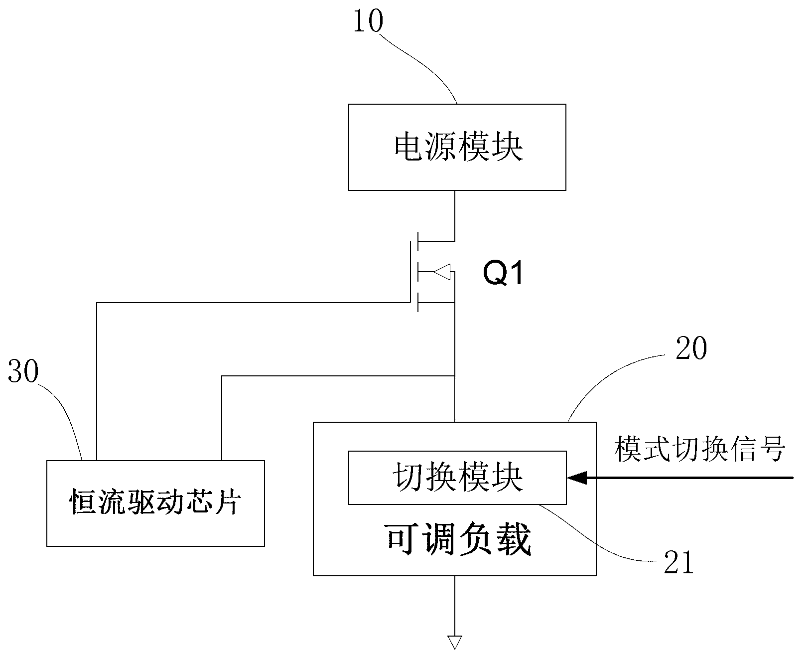
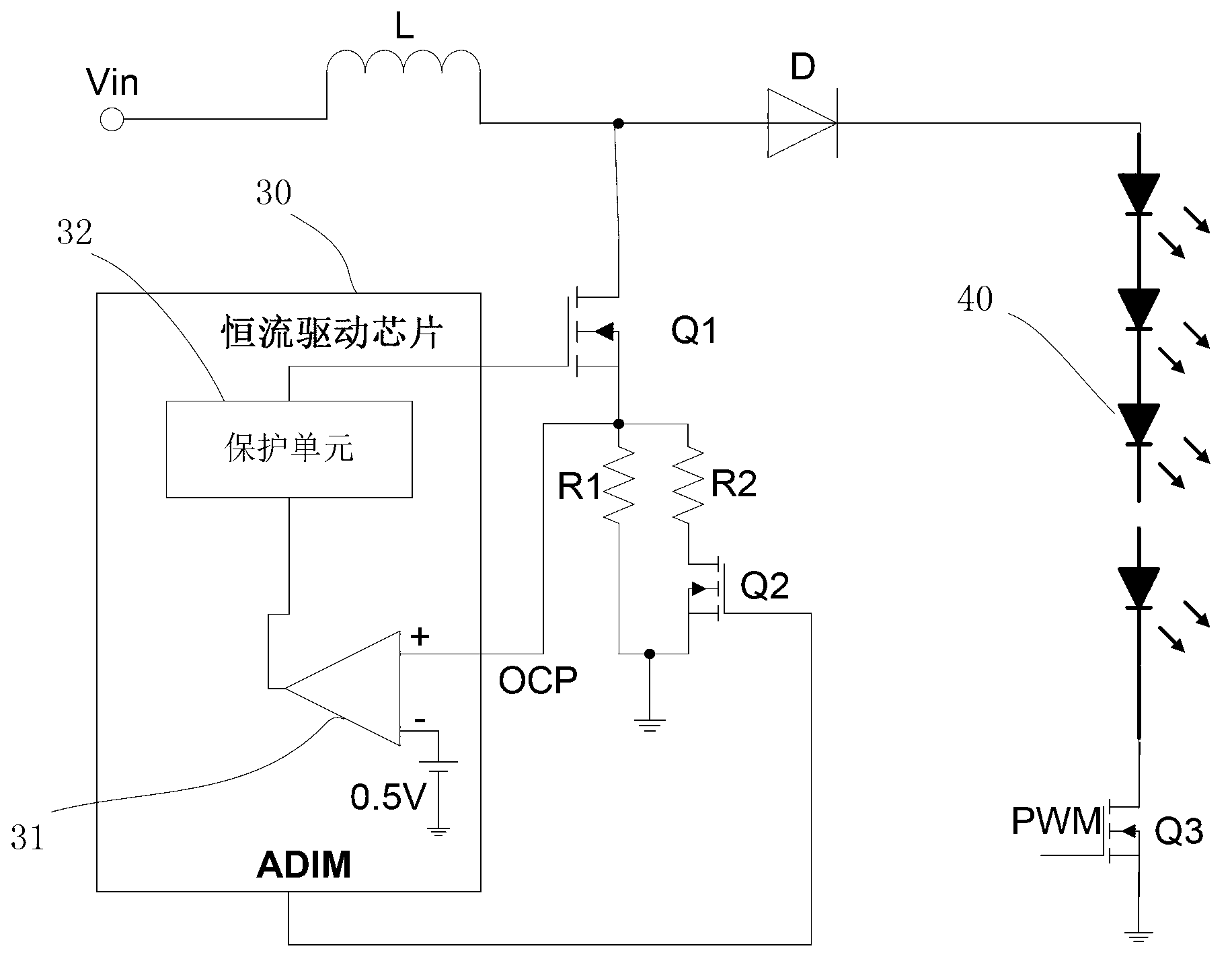
[0030] Such as image 3 , 4As shown, the backlight drive circuit disclosed in this embodiment includes a power module and a constant current drive chip 30, the power module includes a first controllable switch Q1, and an adjustable load is connected between the first controllable switch Q1 and the ground terminal of the backlight drive circuit. , the adjustable load includes a switching module that can switch different resistance values, the control end of the switching module is coupled to the mode switching signal of the backlight drive circuit; the end of the adjustable load connected to the first controllable switch Q1 is coupled to the constant current drive chip 30 overcurrent protection port.

[0031] The adjustable load includes a first resistor R1 and a second resistor R2 connected in parallel, the switching module includes a second controllable switch Q2, and the second controllable switch Q2 is connected in series between the second resistor R2 and the ground termi...

Embodiment 2

[0042] Such as Figure 5 As shown, this embodiment discloses a driving method of the backlight driving circuit of the present invention. Include steps:

[0043] A. Determine the display mode of the backlight drive circuit. If it is a 2D display mode, go to step B; if it is a 3D display mode, go to step C;

[0044] B. The mode switching signal controls the switching module to switch to the resistance value corresponding to the 2D overcurrent protection threshold;

[0045] C. The mode switching signal controls the switching module to switch to the resistance value corresponding to the 3D overcurrent protection threshold;

[0046] The adjustable load can adopt the scheme of connecting resistors in parallel, specifically, the adjustable load includes a first resistor and a second resistor connected in parallel, the switching module includes a second controllable switch, and the second controllable switch is connected in series between the second resistor and ground between the ...


PUM


Abstract

The invention discloses a backlight drive circuit, a driving method thereof and a liquid crystal device. The backlight drive circuit comprises a power module and a constant current driving chip, the power module comprises a first controllable switch, an adjustable load is connected between the first controllable switch and a backlight drive circuit grounding end, the adjustable load comprises a switching module capable of switching different resistance values, a control end of the switching module is coupled to a mode switch signal of the backlight drive circuit, and one end of the adjustable load, which is connected with the first controllable switch, is coupled to an over-current protection port of the constant current driving chip. According to the backlight drive circuit, the driving method thereof and the liquid crystal device, two and even more over-current protection (OCP) threshold values can be provided, and reliable over-current protection can be achieved whether in a 2 dimensional (2D) or 3 dimensional (3D) mode.

Description

technical field [0001] The invention relates to the field of liquid crystal display, and more specifically, relates to a backlight driving circuit, a driving method thereof and a liquid crystal device. Background technique [0002] Usually, the constant current driver chip of the backlight driver circuit will be equipped with an over current protection port (over current protection, hereinafter referred to as OCP) and a corresponding OCP threshold. When the output power of the backlight driver circuit is too large, which may damage the components, the control The backlight drive circuit is disconnected to protect the circuit, the specific circuit is as figure 1 shown. [0003] The current constant current driver chip of the backlight driver circuit has only one OCP threshold, which is generally set according to the 2D display mode. However, in 3D mode, it often happens that the OCP threshold is not reached, the overcurrent protection function has not been triggered, but th...

Claims


Application Information

Patent Timeline
IPC IPC(8): G09G3/34G09G3/36
CPCG09G3/3426G09G2330/025G09G2330/04H05B45/10H05B45/38Y02B20/30
Inventor 胡安乐张先明
Owner SHENZHEN CHINA STAR OPTOELECTRONICS TECH CO LTD
Why Eureka
Try Eureka