
motor control unit

A control device, motor technology, applied in the direction of motor control, AC motor control, control system, etc.

Active Publication Date: 2016-05-04
SANYO DENKI CO LTD
View PDF6 Cites 0 Cited by
  • Summary
  • Abstract
  • Description
  • Claims
  • Application Information

AI Technical Summary

Problems solved by technology

[0015] The present invention is made in order to solve the above-mentioned conventional disadvantageous problems, and the object is to provide a motor control device that does not use many parameters such as motor constants, and does not provide a special detector for calculating electric power, Instead, in the 120° energized power regenerative converter, the electric power monitoring function can monitor the power consumption by using the existing detector installed for the converter control

Method used


Image

  • motor control unit
  • motor control unit
  • motor control unit

Examples


Embodiment Construction

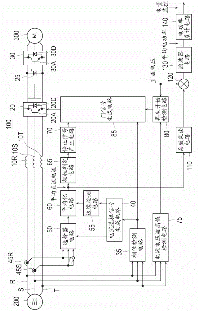
[0048] Next, the motor control device according to this embodiment will be described. figure 1 It is a block diagram of the motor control device of this embodiment.

[0049] [Configuration of motor controller]

[0050] Motor control device 100 includes reactors 10R, 10S, and 10T, inverter unit 20 , capacitor 25 , and inverter unit 30 in order to supply electric power to motor 300 .

[0051] Reactors 10R, 10S, and 10T are connected in series between three-phase power supply 200 and converter unit 20 on respective three-phase power supply lines R, S, and T connecting three-phase power supply 200 and converter unit 20 . The reactors 10R, 10S, and 10T adjust the currents flowing through the three-phase power lines R, S, and T, respectively.

[0052] The converter unit 20 converts the alternating current from the three-phase power supply 200 into direct current. The inverter unit 20 is configured by bridge-connecting six semiconductor switching elements. The semiconductor switc...


PUM


Abstract

The invention provides a motor control device, which monitors electric power consumption of a machine tool. The motor control device (100) comprises a phase detecting circuit (35) which detects a multi-phase AC voltage of a multi-phase power supply, a selector circuit (50) which selects AC current of a specific phase based on the phase detected by the phase detecting circuit (35) and shifts the AC current into DC current, an averaging circuit (60) which equalizes the DC current shifted by the selector circuit to generate an average DC current, a coefficient multiply circuit (110) which uses the average DC current to multiply the coefficient, an electric power operational circuit (120) which multiplies the average DC current multiplied with the coefficient in the coefficient multiply circuit with a DC current at a loading side of a convertor unit, and an electric power accumulating circuit (140) which conducts integration on the electric power calculated by the electric power accumulating circuit according to time to calculate the accumulated electric power.

Description

technical field [0001] The invention relates to a motor control device with electric power monitoring function. Background technique [0002] In recent years, in production plants, stricter management of power consumption in the plants has been required. Therefore, the power consumption of the main machine installed in the production plant is individually monitored. For example, in an electric injection molding machine or a main machine, in order to know the power consumption of the main machine, an electric power monitoring function is designed in the motor control device that controls the operation of the main machine. [0003] A motor control device used in an electric injection molding machine or the like generally includes a converter for rectifying an alternating current and a plurality of inverters for driving the motor. As a method of monitoring the power consumption by the motor control device, for example, there are the following four methods: first to fourth met...

Claims


Application Information

Patent Timeline
Patent Type & Authority Patents(China)
IPC IPC(8): H02P27/08H02P27/06H02P29/00
CPCH02P27/06H02P29/00
Inventor 井出勇治
Owner SANYO DENKI CO LTD
Learn More