
Decoupling type surgical device used for peritoneoscope minimally invasive surgery

A technology of minimally invasive surgery and surgical devices, which is applied in the fields of surgery, application, medical science, etc., can solve the problems of inconvenient control of the system, achieve the effect of improving the flexibility and accuracy of movement, simple control, and not easy to deviate

Inactive Publication Date: 2013-06-26
苏州信诺泰克医疗科技有限公司
View PDF5 Cites 23 Cited by
  • Summary
  • Abstract
  • Description
  • Claims
  • Application Information

AI Technical Summary

Problems solved by technology

[0003] In order to solve the problem that the existing surgical instruments are non-decoupled and the system control is very inconvenient during the operation, the present invention further proposes a decoupled surgical device for laparoscopic minimally invasive surgery

Method used


Image

  • Decoupling type surgical device used for peritoneoscope minimally invasive surgery
  • Decoupling type surgical device used for peritoneoscope minimally invasive surgery
  • Decoupling type surgical device used for peritoneoscope minimally invasive surgery

Examples


specific Embodiment approach 1

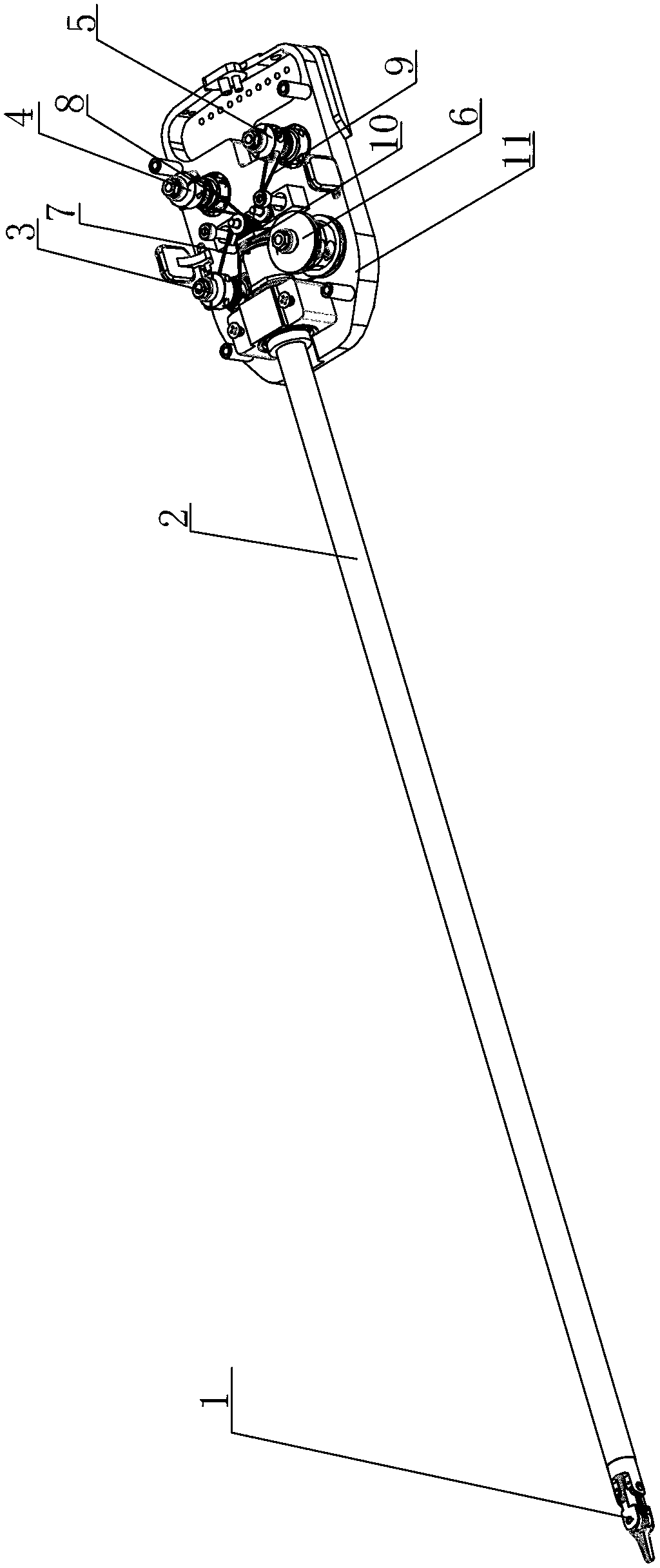
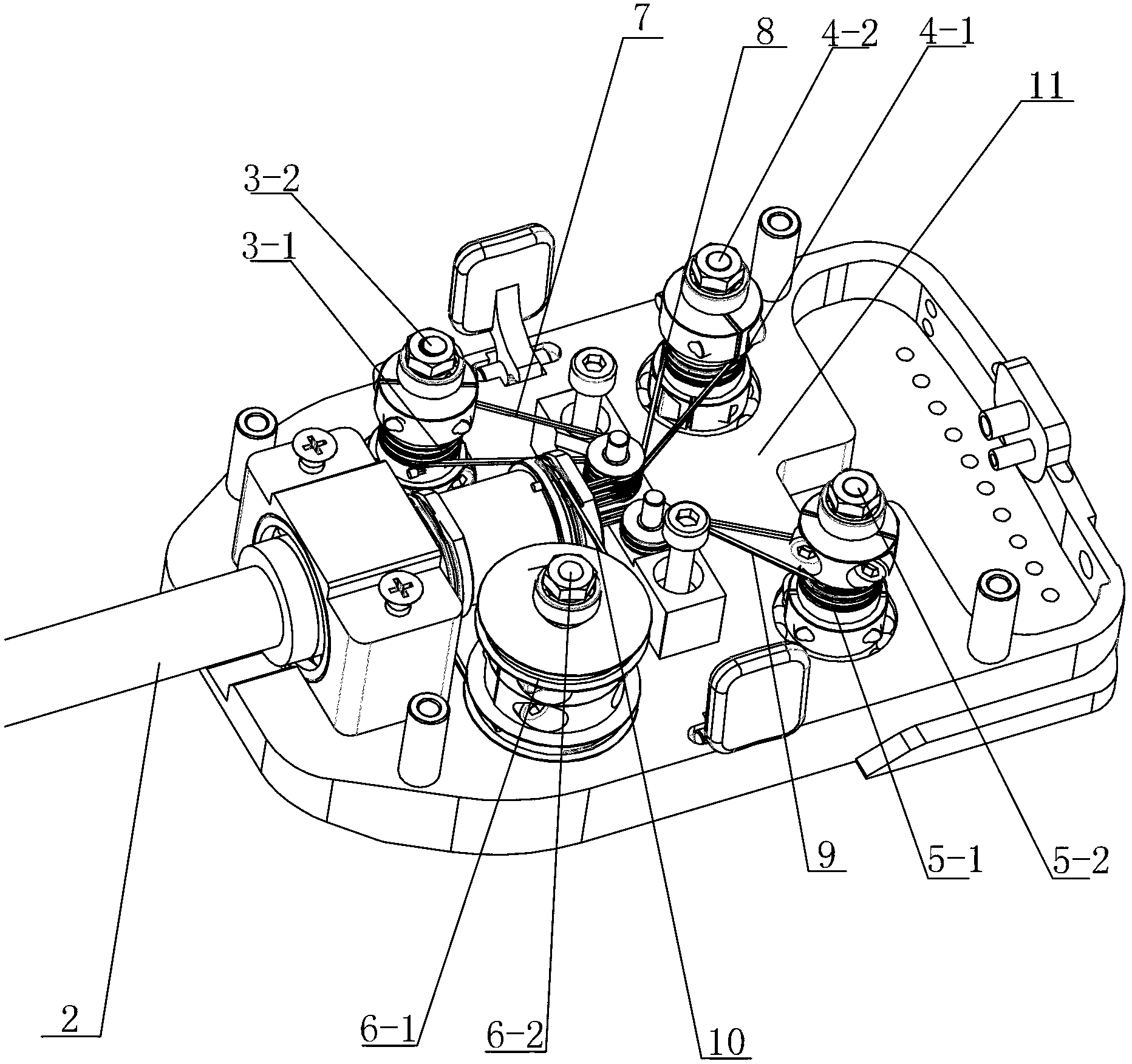
[0007] Embodiment 1: Combining figure 1 Illustrating this embodiment, a decoupling surgical device for laparoscopic minimally invasive surgery described in this embodiment includes a separation forceps mechanism 1 , a rotating rod 2 , a first rotating shaft mechanism 3 , a second rotating shaft mechanism 4 , and a third rotating shaft Mechanism 5, the fourth rotating shaft mechanism 6, the first transmission rope 7, the second transmission rope 8, the third transmission rope 9, the fourth transmission rope 10 and the control box 11, one end of the rotary rod 2 is connected with the separation clamp mechanism 1, The other end of the rod 2 is connected to the control box 11, the first rotating shaft mechanism 3, the second rotating shaft mechanism 4, the third rotating shaft mechanism 5, and the fourth rotating shaft mechanism 6 are installed in the control box 11 in a matrix shape, and the first rotating shaft mechanism 3 passes through The first transmission rope 7 is connecte...

specific Embodiment approach 2

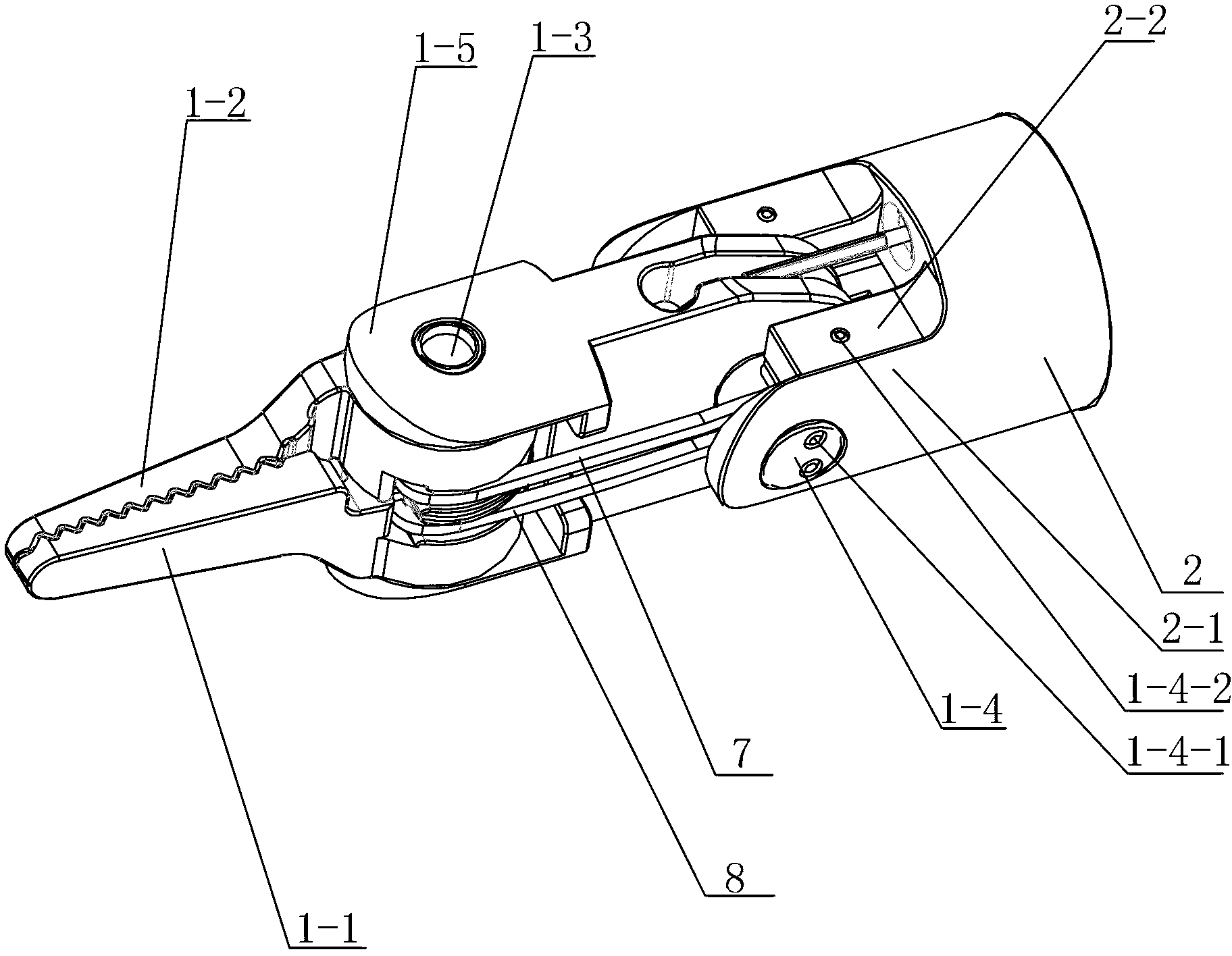
[0008] Specific implementation mode 2: Combining image 3 This embodiment will be described. The separation forceps mechanism 1 of a decoupling surgical device for laparoscopic minimally invasive surgery described in this embodiment includes a first forceps head 1-1, a second forceps head 1-2, and a closing shaft 1 -3. The pitch axis assembly 1-4 and the wrist part 1-5, the root end of the first clamp head 1-1 and the root end of the second clamp head 1-2 are connected through the closed axis 1-3, and the closed axis 1-3 Installed on the front end of the wrist 1-5, the rear end of the wrist 1-5 is connected with the U-shaped notch 2-1 at one end of the rotary rod 2 through the pitch shaft assembly 1-4, and the first rotating shaft mechanism 3 passes through the first transmission rope 7. Connected with the first clamp head 1-1, the first transmission shaft mechanism 3 is used to control the rotation of the first clamp head 1-1 around the closing shaft 1-3, and the second rotat...

specific Embodiment approach 3

[0011] Specific implementation three: combination image 3 and Figure 4 Illustrating this embodiment, the pitch axis assembly 1-4 of a decoupling surgical device for laparoscopic minimally invasive surgery described in this embodiment includes two first decoupling axes 1-4-1 and two second decoupling axes 1-4-1. After decoupling, go to 1-4-2. The two first decoupling shafts 1-4-1 are arranged side by side in parallel, and the two ends of each first decoupling shaft 1-4-1 are respectively connected to the U on one end of the rotary rod 2. The two inner side walls of the U-shaped notch 2-1 are connected correspondingly, and a second decoupling shaft 1-4-2 is respectively installed on the boss 2-2 on each inner side wall of the U-shaped notch 2-1, and each The axes of the two decoupling shafts 1-4-2 are both perpendicular to the axes of the first decoupling shafts 1-4-1, and the first transmission rope 7 and the second transmission rope 8 are both located on the two first decou...


PUM


Abstract

The invention relates to surgical devices used for peritoneoscope minimally invasive surgery, in particular to a decoupling type surgical device used for the peritoneoscope minimally invasive surgery, and aims at solving the problem that existing surgical instruments are not in a decoupling form, so that control of a system in a surgery process is quite inconvenient. The decoupling type surgical device used for the peritoneoscope minimally invasive surgery comprises a first rotating shaft mechanism, a second rotating shaft mechanism, a third rotating shaft mechanism and a fourth rotating shaft mechanism, wherein the first rotating shaft mechanism, the second rotating shaft mechanism, the third rotating shaft mechanism and the fourth rotating shaft mechanism are mounted in a control box in a matrix-shaped mode. The first rotating shaft mechanism is connected with a separating pliers mechanism through a first transmission rope and controls the separating pliers mechanism to be opened through the first transmission rope. The third rotating shaft mechanism is connected with the separating pliers mechanism through a third transmission rope and controls the pitching actions of the separating pliers mechanism through the third transmission rope. The fourth rotating shaft mechanism is connected with the other end of a rotary rod through a fourth transmission rope and controls the rotary motion of the rotary rod through the fourth transmission rope. The decoupling type surgical device used for the peritoneoscope minimally invasive surgery is used in the medical field.

Description

technical field [0001] The invention relates to a surgical device for laparoscopic minimally invasive surgery, in particular to a decoupling surgical device for laparoscopic minimally invasive surgery. Background technique [0002] Minimally invasive surgical technology has made most surgical operations bid farewell to the open surgical model. The application of robotic technology to medical surgery has been highly valued by countries around the world. Robots have unparalleled operational stability, speed and accuracy. Advantages, the integration of robotic technology into surgical operations can improve the operating environment of doctors and shorten the recovery time of patients. The current robotic minimally invasive surgery is mainly performed by making multiple tiny incisions on the patient. Usually, one incision is used for surgery. For the introduction of endoscopes, other incisions are used for the introduction of surgical instruments for surgical operations. Gener...

Claims


Application Information

Patent Timeline
Patent Type & Authority Applications(China)
IPC IPC(8): A61B19/00A61B17/00
Inventor 李海洋杜志江董为郝亚强
Owner 苏州信诺泰克医疗科技有限公司
Learn More