Tin-fried smoke guide hood structure in tin plating process

A smoke guide cover and tin plating technology, which is applied in hot-dip plating process, metal material coating process, coating, etc., can solve the problems of harsh workshop environment, no acid smoke discharge structure, etc., achieve good heat preservation effect, solve Frying tin spatter problem, the effect of reducing energy consumption

Inactive Publication Date: 2013-06-26
ZHUHAI ZHONGJING MACHINERY
View PDF8 Cites 0 Cited by
  • Summary
  • Abstract
  • Description
  • Claims
  • Application Information

AI Technical Summary

Problems solved by technology

[0009] The technical problem to be solved by the present invention is to overcome the problem that the prior art tinning device does not have an acid smog discharge structure, and the acid smog produced when the flux enters the tin pot cannot be efficiently and organizedly discharged, resulting in bad workshop environment and waste gas The defect of excessive flow can meet people's wishes, and a tin-fried fume guide structure in the tin plating process is provided. Effective and organized discharge, minimize the spread of acid fumes in the workshop, and solve the problem of frying tin spatter, reduce the waste of tin, improve the working environment of the workshop, and minimize the impact of acid fumes and splashed frying tin on operators It is harmful to the body, and can reduce the flow of exhaust gas to reduce the difficulty of centralized treatment of exhaust gas. In addition to improving the internal environment of the workshop, it also provides conditions for centralized treatment to avoid air pollution

Method used


Image

  • Tin-fried smoke guide hood structure in tin plating process
  • Tin-fried smoke guide hood structure in tin plating process
  • Tin-fried smoke guide hood structure in tin plating process

Examples


Embodiment Construction

[0031] The present invention will be described in further detail below in conjunction with the accompanying drawings and specific embodiments, and the implementation scope of the present invention is not limited thereto.

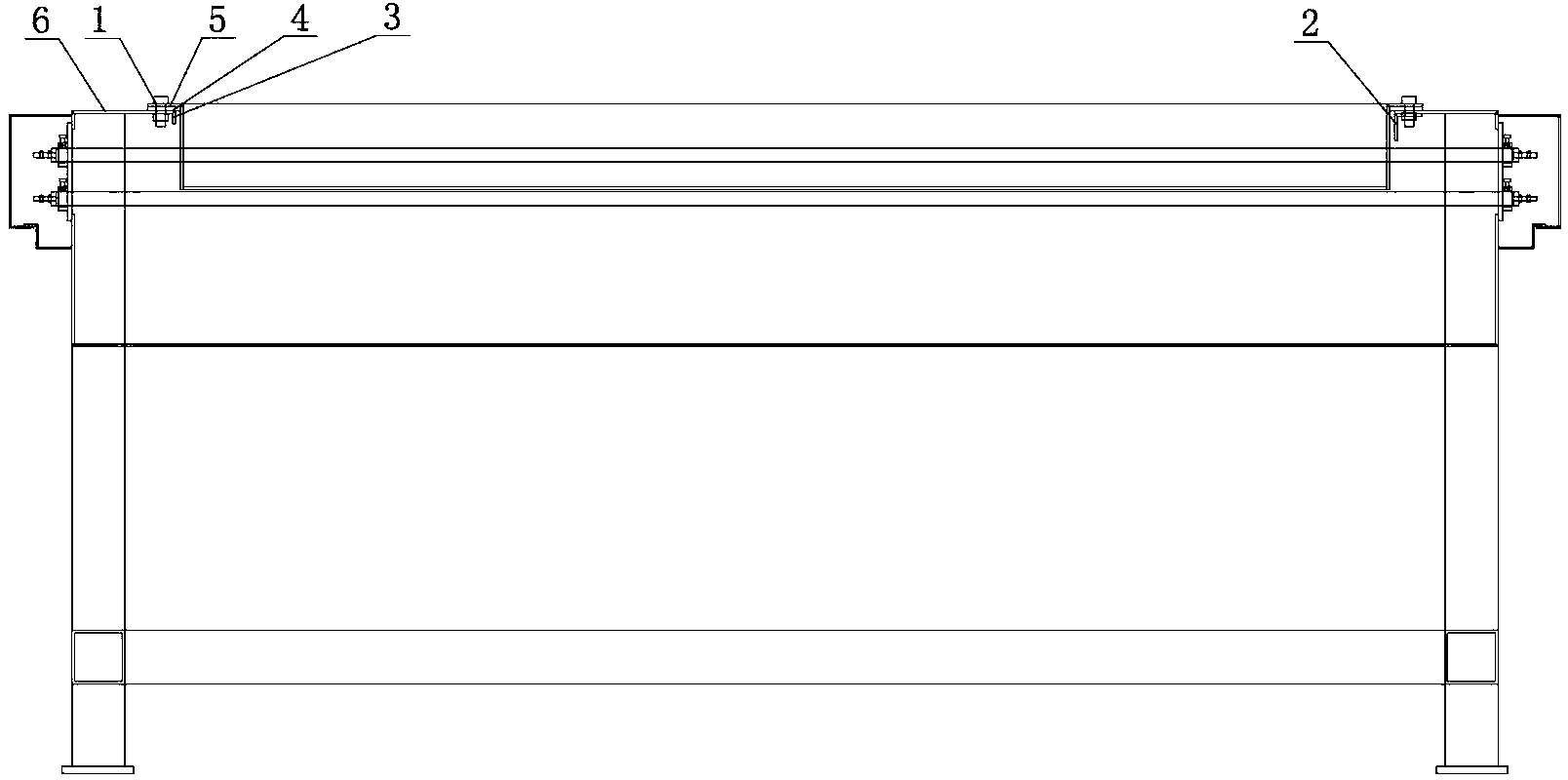
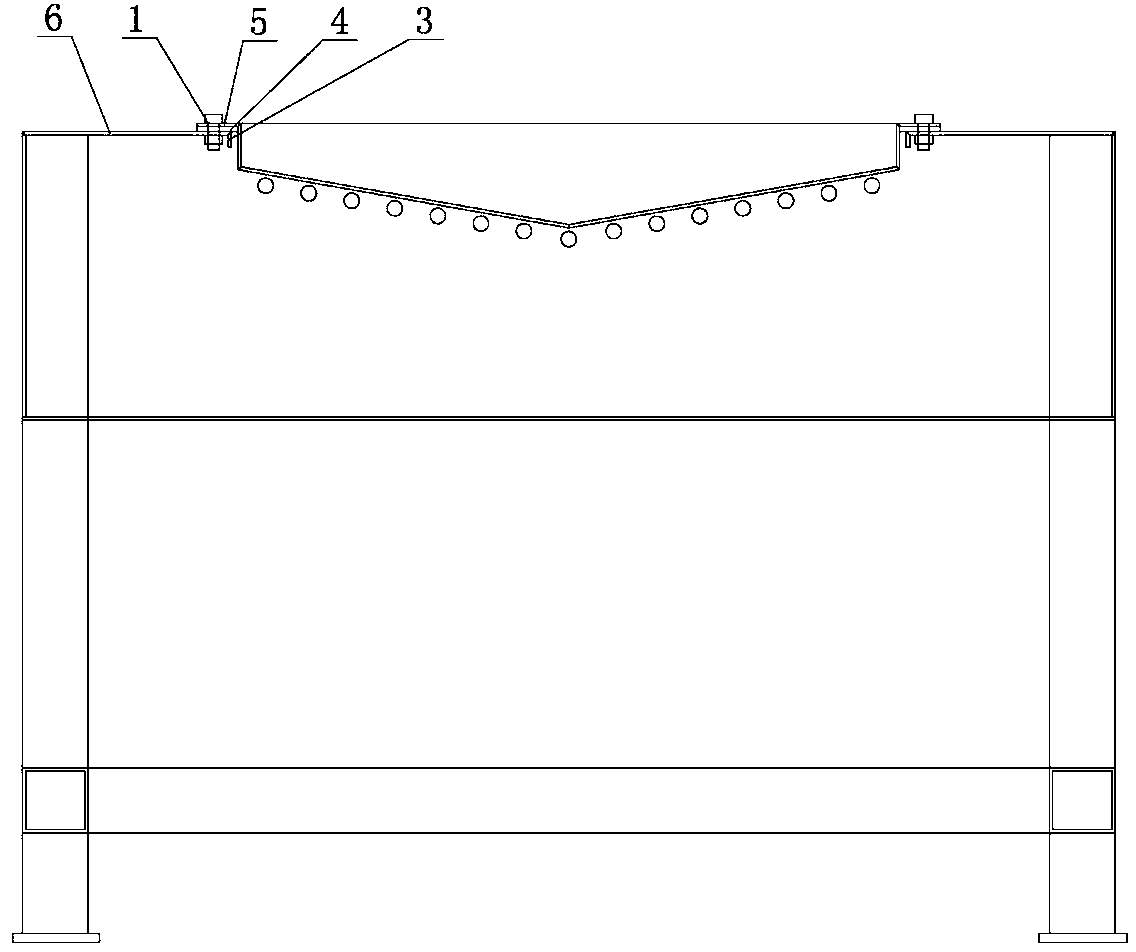
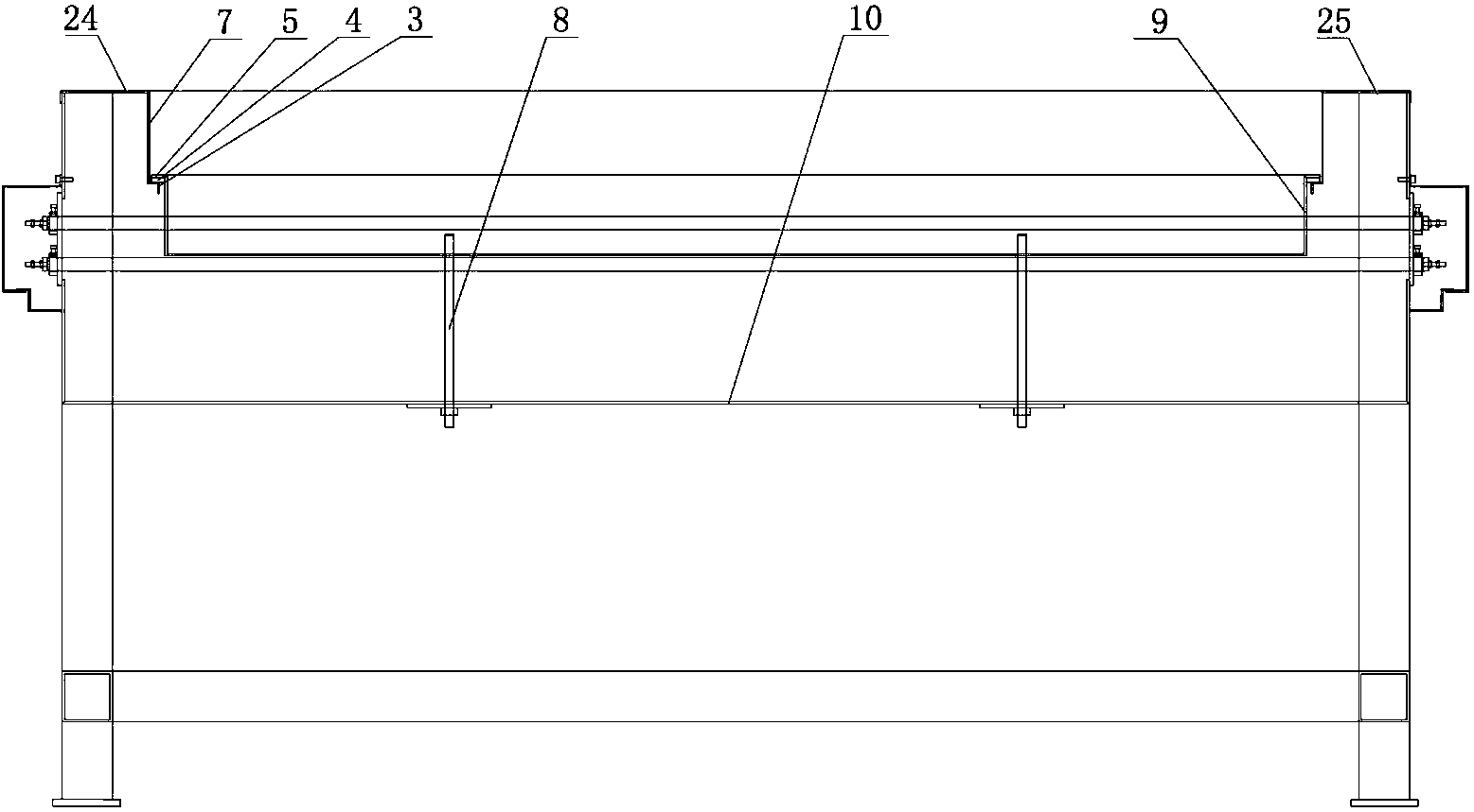
[0032] like Figure 3 to Figure 9As shown, the tin frying fume hood structure in a tinning process described in this embodiment includes a tin frying cover 14, and also includes a left turning shaft support 12, a left turning bracket 13, and a right turning shaft support 22. , the right turning bracket 23, the smoke guide cover 15 and the tin tank 16, the left turning shaft support 12 is installed on the left side table 24 in the pot edge table structure near the incoming line end of the tin pot 9, and the left turning bracket 13 Installed on the left turning shaft support 12, the right turning shaft support 22 is installed on the right side table 25 in the pot edge table structure near the incoming line end of the tin pot 9, and the right turning bracket 23...


PUM


Abstract

The invention discloses a tin-fried smoke guide hood structure in a tin plating process, which comprises a tin-fried cover, a left turning shaft support, a left turning bracket, a right turning shaft support, a right turning bracket, a smoke guide hood and a tin receiving tank, wherein the wire inlet end of the left turning shaft support close to a tin pan is arranged on a left mesa in a pan-edge mesa structure, the left turning bracket is arranged on the left turning shaft support, the wire inlet end of the right turning shaft support close to a tin pan is arranged on a right mesa in the pan-edge mesa structure, the right turning bracket is arranged on the right turning shaft support, the tin receiving tank is arranged at the wire inlet side of the tin-fried cover, the smoke guide hood is fixedly welded at the wire outlet side of the tin-fried cover, and the tin-fried cover, the tin receiving tank and the smoke guide hood as a whole are connected to the left turning shaft support and the right turning shaft support through a turning shaft. The tin-fried smoke guide hood structure in the tin plating process can achieve an effective organized discharge effect on acidic smoke generated in the tin pan, thereby minimizing the spreading of acidic smoke in workshops, and improving the workshop environment; and the tin-fried smoke guide hood structure can solve the problem of tin fried splashing, thereby reducing the waste of tin.

Description

technical field [0001] The invention relates to the technical field of tinning devices, in particular to a tin-fried fume guide structure in the tinning process. Background technique [0002] Tinned wire (copper wire, alloy wire, etc.) is widely used in industry, so the production of tinned wire occupies a large proportion in wire production. The traditional tinning device has the following problems that cannot be completely solved for a long time: 1. The acid fume generated when the flux enters the tin pot cannot be effectively and organizedly discharged, resulting in a bad workshop environment; 2. The temperature in the tin pot is uneven, The process conditions of each wire are inconsistent, which affects the product quality; 3. No effective protective measures are taken for the splashing of fried tin, which is prone to scalding the operator and destroys the workshop environment, and increases the waste of tin; 4. Poor insulation and high energy consumption. [0003] Org...

Claims


Application Information

Patent Timeline
Patent Type & Authority Applications(China)
IPC IPC(8): C23C2/08C23C2/38
Inventor 周兴和
Owner ZHUHAI ZHONGJING MACHINERY
Why Eureka
Try Eureka