
Sampling device for well-inside in-situ fluid in deep well

A sampling device, an in-situ technology, applied in wellbore/well components, earth-moving drilling, etc., can solve the problems of narrow downhole space, formation fluid pollution, formation fluid disturbance, etc., and achieve small size, stable performance and low cost. Effect

Active Publication Date: 2013-06-26
天津星通九恒科技有限公司
View PDF8 Cites 12 Cited by
  • Summary
  • Abstract
  • Description
  • Claims
  • Application Information

AI Technical Summary

Problems solved by technology

However, there are considerable difficulties in collecting undisturbed underground fluid. First, the drilling fluid will pollute the formation fluid during drilling and well formation; second, the technological means in the sampling process will disturb the formation fluid and affect its original state; third , the downhole space is narrow, and there is a high liquid column pressure, deep fluid sampling requires reasonable structural design and high performance requirements for sampling equipment
At present, there is no downhole fluid pneumatic sampling technology and equipment with a depth of more than 500 meters in China

Method used


Image

  • Sampling device for well-inside in-situ fluid in deep well
  • Sampling device for well-inside in-situ fluid in deep well
  • Sampling device for well-inside in-situ fluid in deep well

Examples


Embodiment Construction

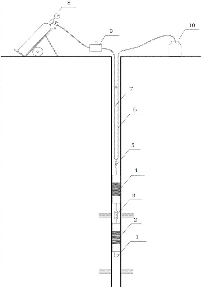
[0031] see figure 1 As shown, it is an embodiment of the in-situ fluid sampling device in a deep well of the present invention. In this embodiment, the in-situ fluid sampling device in a deep well is composed of a downhole unit and an uphole unit. The downhole unit is responsible for positioning the sampling target layer and isolating non-sampling Fluid, allowing sampling fluid to enter the sampling system, etc., mainly including plug 1, lower packer 2, filter screen 3, upper packer 4, water inlet window 5, sampling pipe 6 and gas supply pipe 7. The uphole unit is responsible for controlling the sampling and receiving the sampling fluid collected to the surface, mainly including high-pressure N 2 Gas cylinder 8, air conditioner 9 and aseptic sampling bottle 10.

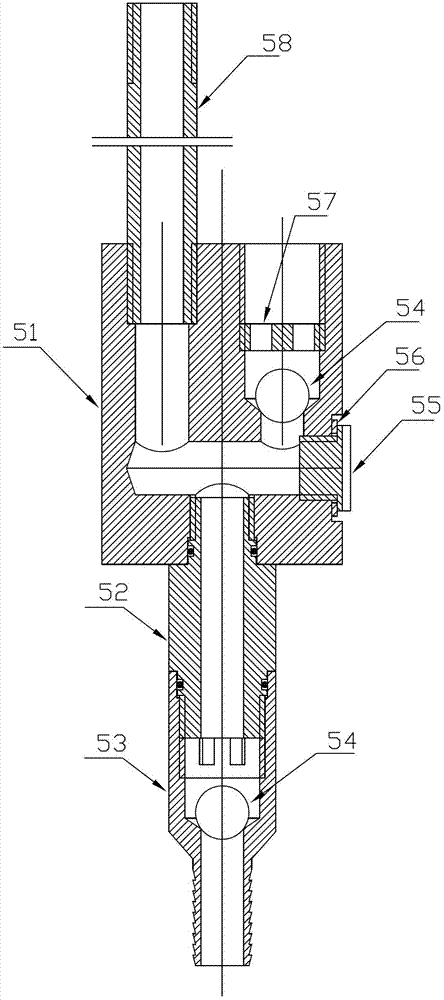
[0032] The water inlet window 5 is processed from stainless steel. Inlet window allows sample fluid to enter sampling line 6 and prevents backflow, see figure 2 , The water inlet window is made up of base 51, chec...


PUM

PropertyMeasurementUnit
Diameteraaaaaaaaaa
Thicknessaaaaaaaaaa
Widthaaaaaaaaaa

Abstract

The invention discloses a sampling device for well-inside in-situ fluid in a deep well. The sampling device is composed of a downhole sampling unit and a pit unit. The pit unit comprises a set of air supply sources controlled by an air regulator and a set of containers used for collecting samplings. The downhole sampling unit is provided with a water inlet window, an upper packer, a filtering screen unit and a lower packer, wherein the water inlet window, the upper packer, the filtering screen unit and the lower packer are sequentially arranged from top to bottom, and the water inlet window has a double-check function. The water inlet window comprises a base seat, wherein three channels are formed on the base seat and include a water inlet channel with a downward opening, a water outlet channel with an upward opening and an air supplying channel with an upward opening. The water inlet channel is controlled by a lower one-way valve, and sampling flow liquid flows in unidirectionally. The water outlet channel with the upward opening is controlled by an upper one-way valve, the sampling flow liquid flows out unidirectionally, and the water outlet channel is connected to the containers used for collecting the samplings through sampling pipes. The air supplying channel with the upward opening is communicated with the air supply sources of the pit unit through air supply pipes. The sampling device can conveniently and rapidly extract the samplings of the well-inside in-situ fluid in the deep well.

Description

technical field [0001] The invention relates to a downhole fluid sampling technology, in particular to a device for sampling in-situ fluid in a well under conditions of deep well and narrow space. Background technique [0002] Deep formation fluid samples can provide subsurface fluid chemical characteristics, isotopic composition, dissolved gas and microbial characteristics, etc., and have deep space physical, chemical and biological information, which is of great significance to deep well design and development and deep fluid monitoring. It is an important component of deep well engineering part. However, there are considerable difficulties in collecting undisturbed underground fluids. First, the drilling fluid will pollute the formation fluid during the drilling and well formation process; second, the technological means in the sampling process will disturb the formation fluid and affect its original state; third, , the downhole space is narrow, and there is a high liquid...

Claims


Application Information

Patent Timeline
IPC IPC(8): E21B49/08
Inventor 李小杰潘德元郑继天叶成明李炳平王建增关晓琳
Owner 天津星通九恒科技有限公司
Learn More