Static strength and fatigue test device for tumbler type shaft housing as well as its method

A fatigue test and test device technology, applied in the field of rail transit, can solve the problems of distortion of the experimental data of the axle box, inability to obtain, ignoring the effect of the shock absorber, etc., to achieve the effect of standardization and improvement of rationality

Inactive Publication Date: 2013-06-26
CRRC QINGDAO SIFANG CO LTD
View PDF7 Cites 19 Cited by
  • Summary
  • Abstract
  • Description
  • Claims
  • Application Information

AI Technical Summary

Problems solved by technology

[0007] 1. Connecting the axle box to the frame and conducting tests with the frame at the same time cannot simulate the actual operating state of the axle box, because the static strength test and fatigue test methods of the bogie can only be applied to the frame, not to the axle box
[0008] 2. When testing and assessing the fatigue strength of parts, the line spectrum cannot be completely used (the line spectrum is the parameters such as strain, acceleration, displacement, frequency, vibration and other parameters measured on the specified line on the specified line during the operation of the rail vehicle. The load of the sum of ) should be reasonably decomposed and equivalent to the load that appears in the circuit spectrum, and then loaded to the component after taking its equivalent value, otherwise the axle box will never be generated due to the applied load is too small Fatigue damage, so no correct conclusions can be drawn
[0009] 3. When the axlebox fatigue test is carried out on the existing test bench or line, the influence of the shock absorber on the axlebox is not considered, and the effect of the shock absorber is ignored, and the experimental data of the axlebox will be more distorted

Method used


Image

  • Static strength and fatigue test device for tumbler type shaft housing as well as its method
  • Static strength and fatigue test device for tumbler type shaft housing as well as its method

Examples


Embodiment 1

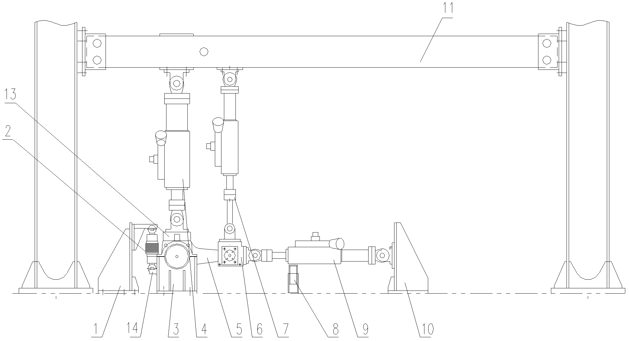
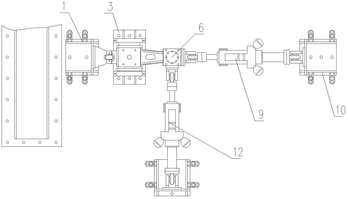
[0035] Example 1, such as figure 1 and figure 2 As shown, the test device for realizing the static strength and fatigue test of the pivoting arm type axle box mainly includes a loading beam 11 and an axle box seat 3 .

[0036] Wherein, the axle box body of the pivoting arm type axle box 5 is fixed on the axle box seat 3, and the axle box spring seat 13 on its top is connected to the first vertical actuator 4; The loading seat 6 , the second vertical actuator 7 , the lateral actuator 9 and the longitudinal actuator 12 are respectively connected to the node loading seat 6 .

[0037] A shock absorber 2 is loaded on the shock absorber seat 14 of the pivoting arm type axle box 5 , and the shock absorber 2 is installed on the shock absorber seat 1 .

[0038] An elastic support 8 is connected to the bottoms of the transverse actuator 9 and the longitudinal actuator 12 mounted on the support 10 .


PUM


Abstract

The invention discloses a static strength and fatigue test device for a tumbler type shaft housing as well as its method. A static strength and fatigue test is implemented independently for the tumbler type shaft housing by taking an equivalent load converted from a line spectrum load, so that the test specifications and flows of loads in a plurality of directions are standardized to obtain a real and accurate shaft housing strength and fatigue test results and further assist in the improvement and optimization of the structure and stress design of the shaft housing. The test device for a static strength and fatigue test method of the tumbler type shaft housing comprises a loading beam and a shaft housing seat. A shaft housing body of the tumbler type shaft housing is fixed on the shaft housing seat. A shaft housing spring seat on the top of the tumbler type shaft housing is connected with a first vertical actuating cylinder. A second vertical actuating cylinder, a transverse actuating cylinder and a longitudinal actuating cylinder are connected to an elastic joint of the tumbler type shaft housing respectively.

Description

technical field [0001] The invention relates to a device and a method for performing static strength and fatigue tests on a rotary arm type axle box alone, and belongs to the technical field of rail transportation. Background technique [0002] With the rapid popularization of domestic urban rail transit and the substantial increase in vehicle speed, higher design and use requirements are put forward for the bogie frame that carries the vehicle body and transmits traction. At present, the primary suspension system of the bogie used in domestic rail transit generally adopts the axle box positioning method, that is, the axle box pivot arm positioning structure, which is usually defined as the pivot arm axle box. [0003] For example, the prior patent application that discloses the following content, the application number is 201020542266.6, and the name is a series of elastic positioning devices for rail vehicles, which are arranged between the bogie frame and the vertical dir...

Claims


Application Information

Patent Timeline
Patent Type & Authority Applications(China)
IPC IPC(8): G01N3/36G01N3/10
Inventor 崔洪举李亚波刘为亚陈一萍盛辉
Owner CRRC QINGDAO SIFANG CO LTD
Why Eureka
Try Eureka