Method for estimating microbubble cluster dimension distribution in evanishment process in solution

A technology of size distribution and microbubbles, which is applied in the field of size detection of cavitation microbubbles, can solve problems such as limitation and difficulty in measuring the size of cavitation microbubbles

Active Publication Date: 2013-06-26
XI AN JIAOTONG UNIV
View PDF1 Cites 2 Cited by
  • Summary
  • Abstract
  • Description
  • Claims
  • Application Information

AI Technical Summary

Problems solved by technology

However, the randomness of the cavitation process makes it difficult to measure the size of cavitation microbubbles. Previous studies have shown that domestic and foreign scholars have mostly studied the estimation methods of c...

Method used


Image

  • Method for estimating microbubble cluster dimension distribution in evanishment process in solution
  • Method for estimating microbubble cluster dimension distribution in evanishment process in solution
  • Method for estimating microbubble cluster dimension distribution in evanishment process in solution

Examples


Embodiment 1

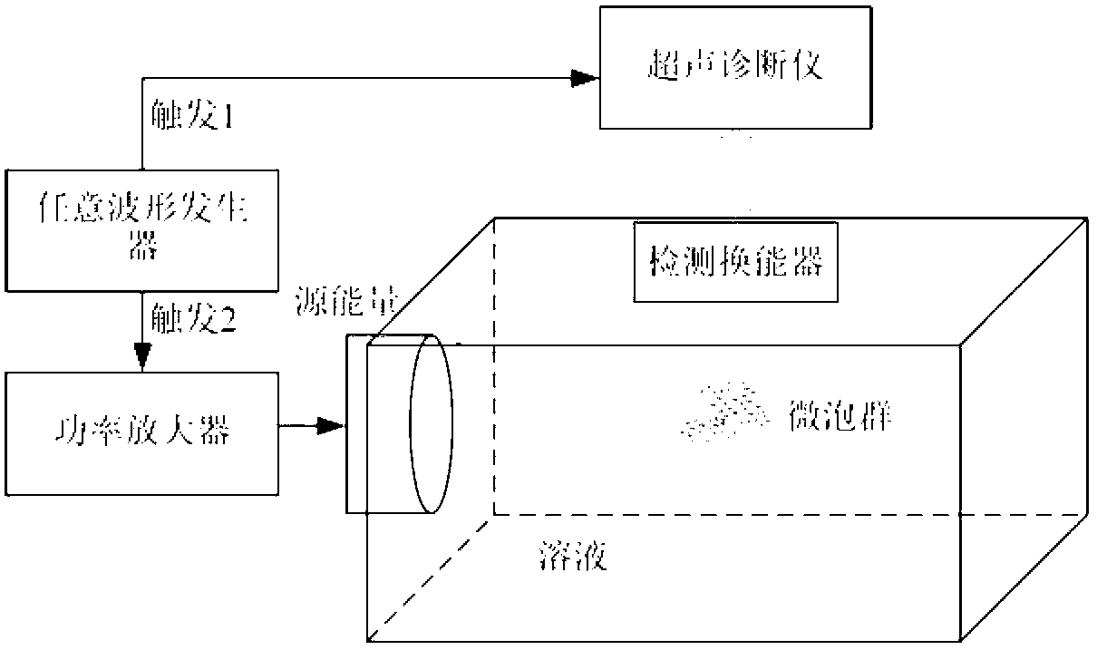
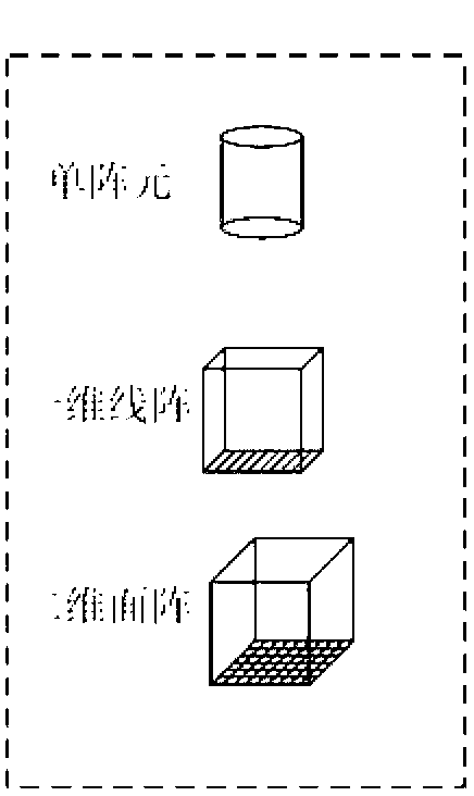
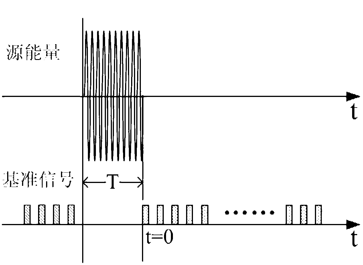
[0076] High-intensity focused ultrasound (HIFU) was used as the energy source, and the sound power was 6W in tap water for 20us. This process is considered to be the process of ultrasonic generation of cavitation microbubbles containing a single gas (air) in a saturated solution, through the one-dimensional linear array plane wave transmission and reception mode, and the reaction cavitation microbubbles obtained according to the above calculation method The change curve of the group backscatter signal intensity with time, that is, the time intensity curve (TIC) such as Figure 6 As shown in (a), the complete dissipation time of air microbubbles with a given radius of 0-15um is obtained by calculating the complete dissipation time of a single gas system, and its complete dissipation time is shown in Figure 6 (b), combining the time-intensity curve of the microbubble group with the complete dissipation time of microbubbles of each radius, that is, at Figure 6 (a) Finding on t...

Embodiment 2

[0078] High-intensity focused ultrasound (HIFU) was used as the energy source, and the sound power was 0.6W for 5ms in the liquid-phase perfluoropentane (C5F12) nanoparticle phase change material solution diluted in tap water. This process is considered to be the process of ultrasonic generation of multi-gas components (air and perfluoropentane from liquid phase to gas phase) cavitation microbubble group in saturated solution, through two-dimensional or one-dimensional linear array or single array element Transmitter plane wave transmission and reception, and the time intensity curve (TIC) of the backscattering signal intensity of the response multi-gas component cavitation microbubble group obtained according to the calculation method described above is as follows: Figure 7 As shown in (a), the multi-gas component air microbubbles with a given radius of 0-15um and the assumed volume ratio of air to perfluoropentane in the microbubbles are obtained by calculating the complete ...


PUM


Abstract

The invention discloses a method for estimating microbubble cluster dimension distribution in an evanishment process in solution, wherein the information of change of backscatter intensity of the microbubble cluster in a source energy radiation volume in the solution, namely a time intensity curve (TIC), is obtained through a two-dimensional area array transducer on a diagnostic ultrasound instrument in a plane wave transmitting/receiving way. The dimension distribution at the initial moment of evanishment of the cavitated microbubble cluster, namely the dimension distribution of the cavitated microbubble cluster generated when the source energy stops acting, is obtained through the obtained microbubble cluster evanishment information, namely the time intensity curve (TIC), and complete evanishment time of microbubbles of an initial radius obtained through calculation. The method provided by the invention realizes estimation of the dimension distribution of the microbubble cluster in the evanishment process of the cavitated microbubble cluster generated in a non-transparent substance in some energy acting forms (such as ultrasonic, microwave and laser) or the combination of the energy forms.

Description

technical field [0001] The invention belongs to the technical field of size detection of cavitation microbubbles, and relates to a method for estimating the size distribution of cavitation microbubbles during the process of dissipating cavitation microbubbles in a solution. Background technique [0002] Cavitation refers to a series of dynamic processes such as oscillation, expansion, contraction, and implosion that cavitation nuclei in liquids exhibit under certain forms of energy action (such as ultrasound, microwave, laser, etc.). The existence of cavitation nuclei is a prerequisite for liquid cavitation, which includes 1. dissolved gas molecules in the liquid (such as dissolved air in water); 2. remaining cavitation nuclei after the previous cavitation; 3. in the liquid The surface roughness of the particles; 4. Cavitation nuclei artificially added to reduce the cavitation threshold (such as phase-change nanoparticles added in biomedical ultrasound treatment). Water con...

Claims


Application Information

Patent Timeline
IPC IPC(8): G01N15/02
Inventor 万明习徐姗姗
Owner XI AN JIAOTONG UNIV
Why Eureka
Try Eureka