
Novel siphon rain gauge

A siphon rain gauge, a new type of technology, applied in the field of rain gauge, can solve the problems of leaky door cover, pointer head replacement, and bell cylinder adding force, etc., and achieve the effect of saving labor and cost

Inactive Publication Date: 2015-01-21
舟山市水利水务围垦局
View PDF7 Cites 0 Cited by
  • Summary
  • Abstract
  • Description
  • Claims
  • Application Information

AI Technical Summary

Problems solved by technology

[0004] The purpose of the present invention is to provide a new type of siphon rain gauge to effectively solve the problems that the bell cylinder of the current siphon type rain gauge needs to be frequently added force, the door cover is not sealed, the recording paper needs to be taken out every day, and the pointer head needs to be replaced frequently

Method used


Image

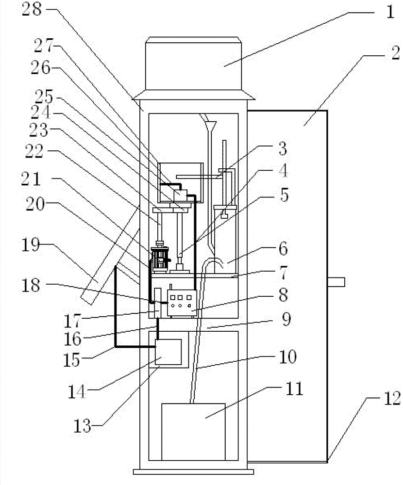
  • Novel siphon rain gauge

Examples


Embodiment Construction

[0017] The present invention will be further described below in conjunction with the accompanying drawings and embodiments.

[0018] As shown in the figure, a new siphon type rain gauge includes a cylinder body 28, a water cup 11, a door cover 2, a bottom plate 7, a partition 9, a buoy 6, a siphon tube 10, a bell cylinder 27, a support 5 and a water inlet circle. Cylinder 1, the water inlet cylinder 1 is set above the cylinder body 28, the water cup 11 is set under the inside of the cylinder body 28, the door cover 2 is set on the right outside of the cylinder body 28, and the partition plate 9 is set on the Above the water cup 11, the bottom plate 7 is arranged above the partition 9, the buoy 6 is arranged on the right above the bottom plate 7, the support 5 is arranged on the left side of the buoy 6, and the bell cylinder 27 is arranged above the support 5, The siphon tube 10 is arranged at the bottom of the buoy 6, a capacitive stylus 3 is arranged above the buoy 6, a gear ...


PUM


Abstract

The invention discloses a novel siphon rain gauge. The novel siphon rain gauge has the advantages that a recording drum is driven by a small motor to rotate, and curves are drawn by an electric handwriting pen and are transmitted to a monitoring station by a data transmitter, so that problems that stress needs to be applied to a recording drum of an existing rain gauge everyday and paper needs to be taken out regularly are solved, and the novel siphon rain gauge is simple in structure, low in cost and suitable for popularization and utilization.

Description

technical field [0001] The invention relates to a rain gauge, in particular to a novel siphon type rain gauge, which belongs to the field of rain gauges. Background technique [0002] The rain gauge is an instrument used by meteorologists and hydrologists to measure the precipitation in a certain area over a period of time. At present, the rain gauge is mainly composed of a water receiver (funnel), a water storage cylinder (outer cylinder), and a water storage bottle. There is a special measuring cup proportional to its caliber. The water receiver is generally set on the top of the rain gauge to collect rainwater into the funnel, and then the rainwater enters the metering device through the funnel. [0003] At present, the existing siphon rain gauges have the following disadvantages: 1. The bell cylinders are all manual and mechanical, and it is necessary to add a force every 24 hours to make the bell cylinders continue to rotate; 2. The door cover is not sealed after it is ...

Claims


Application Information

Patent Timeline
Patent Type & Authority Patents(China)
IPC IPC(8): G01W1/14
Inventor 翁益松陈钺
Owner 舟山市水利水务围垦局
Learn More