
Flash memory test method

A test method and flash memory technology, applied in static memory, instruments, etc., can solve problems such as failure to use flash memory normally, damage to memory areas, etc., and achieve the effect of prolonging service life and reducing costs

Inactive Publication Date: 2013-06-26
FLUIDITECH IP
View PDF5 Cites 7 Cited by
  • Summary
  • Abstract
  • Description
  • Claims
  • Application Information

AI Technical Summary

Problems solved by technology

However, taking flash memory as an example, it may be found that only part of the memory area can be used normally after recovery. Use the 64G flash memory normally, and then discard the flash memory

Method used


Image

  • Flash memory test method
  • Flash memory test method
  • Flash memory test method

Examples


Embodiment Construction

[0035] In order to fully understand the purpose, features and effects of the present invention, the present invention will be described in detail by means of the following specific embodiments and accompanying drawings, as follows:

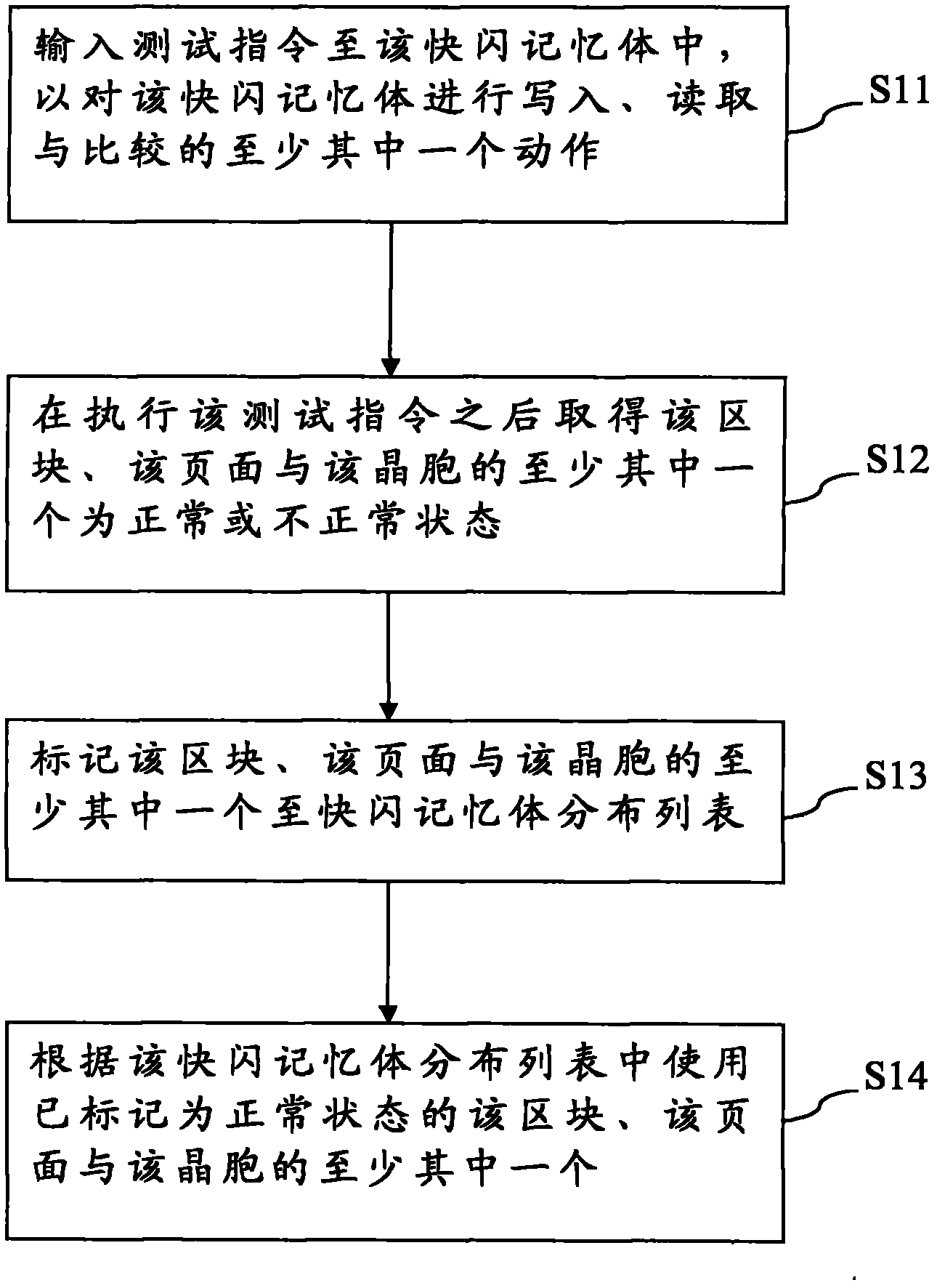
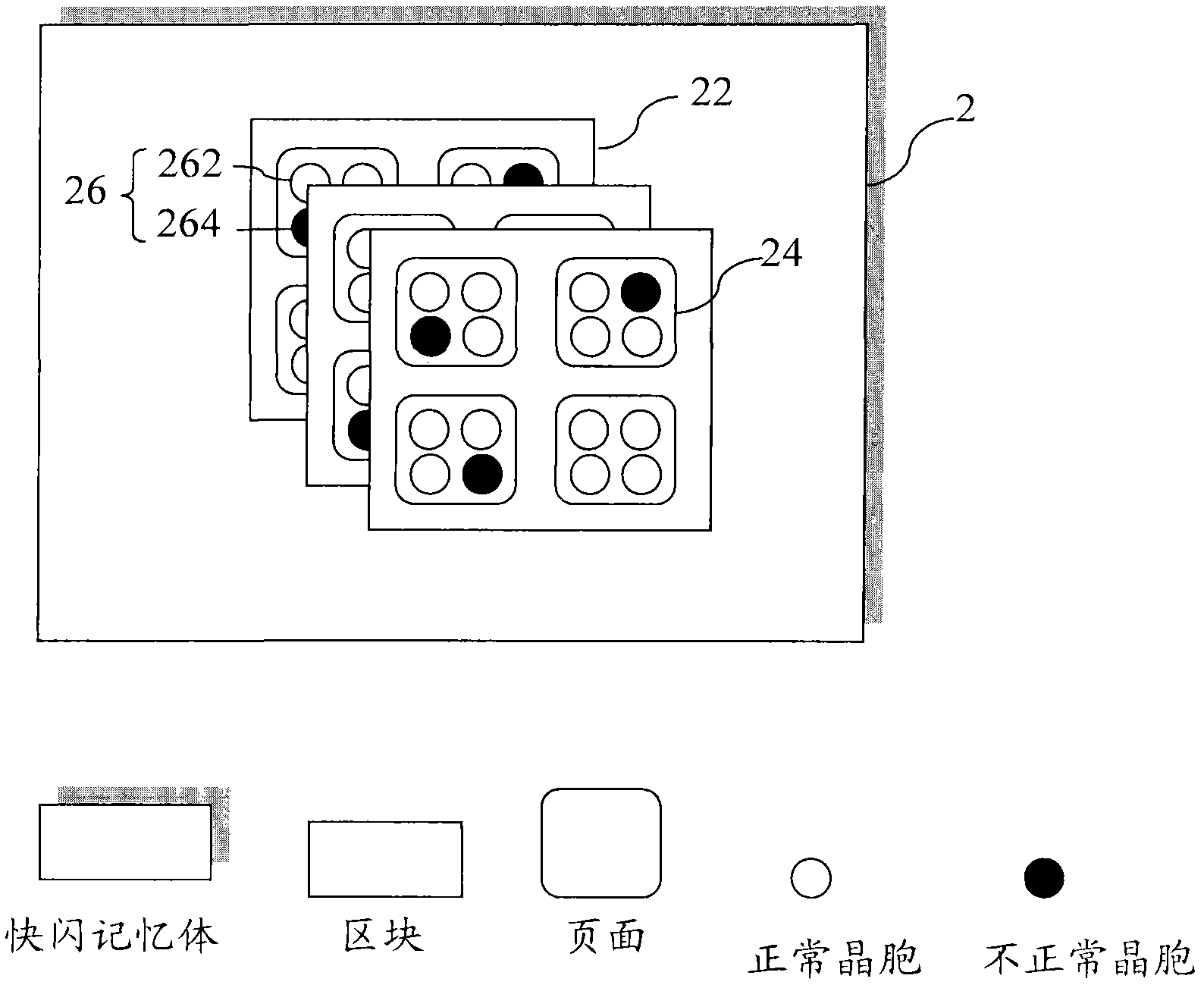
[0036] refer to figure 1 , is a method flowchart of the flash memory testing method according to the first embodiment of the present invention. exist figure 1 In , the flash testing method is applied to sort out defective flash memory for recycling into usable flash memory. Wherein, the flash memory 2 at least includes memory areas such as a block 22, a page 24, and a unit cell 26, and the unit cell 26 also includes a normal unit cell 262 and an abnormal unit cell 264, such as figure 2 shown. Furthermore, the normal unit cell 262 is defined as being able to provide data access normally; on the contrary, the abnormal unit cell 264 cannot normally perform data access.

[0037] The method steps of the flash memory testing method start at step S1...


PUM


Abstract

A flash memory test method is used for choosing a flash memory having defects to recover a usable flash memory, wherein the flash memory at least includes a block, a page and a cell. The method comprises the following steps: inputting a test instruction to the flash memory, writing in, reading or comparing the flash memory, executing the test instruction to obtain the states of the block, the page and the cell in the flash memory, and marking the states in a flash memory distribution list to make a controller access at least one of the block, the page and the cell in a normal state through the flash memory distribution list. The block, the page and the cell for the normal use can be obtained through the test of the flash memory in the invention.

Description

technical field [0001] The invention relates to a flash memory testing method, in particular to a method for selecting out defective flash memory to reclaim usable flash memory. Background technique [0002] Traditionally, a flash memory with memory areas (including blocks, pages, and cells) will age, decay and be damaged over time, which will lead to unusable electronic devices using the flash memory. [0003] Taking electronic products (such as smart phones, digital cameras, memory cards, etc.) using the flash memory as an example, when the electronic product is used for two or three years, it may be defective or returned to the electronic product through the recycling system. The original manufacturer of electronic products. Traditionally, the original manufacturer will disassemble the electronic product to recycle usable units such as LCD display panels, printed circuit boards, and flash memory (such as NAND flash memory), and after assembly, testing and packaging again...

Claims


Application Information

Patent Timeline
IPC IPC(8): G11C29/56
Inventor 储永强
Owner FLUIDITECH IP
Learn More