
Method and device of transmission channel

A transmission channel and channel technology, applied in the field of transmission channels, can solve the problems of large transmission type granularity, inaccurate link loss, uncertain time-frequency resources, etc.

Active Publication Date: 2013-06-26
NANTONG HANGDA ELECTRONICS TECH
View PDF3 Cites 41 Cited by
  • Summary
  • Abstract
  • Description
  • Claims
  • Application Information

AI Technical Summary

Problems solved by technology

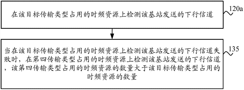
[0005] However, in the prior art, the time-frequency resources occupied by different transmission types are uncertain, and the granularity of determining the transmission type by link loss range is too large
The simulation proves that the link loss of 1dB needs to be repeated twice as many times in time to compensate for the link loss of 1dB through combined reception. Therefore, the existing technology cannot target all super UEs within a certain link loss range have a better enhancement effect
In addition, for some super UEs, for example, UEs located in the basement, the transmission method of the downlink reference signal leads to low received energy of the super UE, and the link loss measured by the super UE may be inaccurate. The parameters may not really be suitable for the current super UE; and when the super UE accesses the base station, the number of repeated transmissions it needs may change. If the number of transmissions in the transmission type determined at the time of initial access is still used, As a result, the super UE cannot receive downlink data or send uplink data accurately, which greatly reduces the enhancement effect of the super UE, and the enhancement effect of the cell coverage needs to be further improved

Method used


Image

  • Method and device of transmission channel
  • Method and device of transmission channel
  • Method and device of transmission channel

Examples


Embodiment Construction

[0122] The technical solutions in the embodiments of the present invention will be clearly and completely described below in conjunction with the accompanying drawings in the embodiments of the present invention. Obviously, the described embodiments are a part of the embodiments of the present invention, rather than all the embodiments. Based on the embodiments of the present invention, all other embodiments obtained by those of ordinary skill in the art without creative work shall fall within the protection scope of the present invention.

[0123] It should be understood that the technical solutions of the embodiments of the present invention can be applied to various communication systems, for example: Global System of Mobile communication (GSM) system, Code Division Multiple Access (Code Division Multiple Access, abbreviated as “CDMA”) system, Wideband Code Division Multiple Access (“WCDMA”) system, General Packet Radio Service (“GPRS”), Long Term Evolution (Long Term Evolution...


PUM


Abstract

The invention discloses a method and a device of a transmission channel. The method comprises the following steps of: determining the transmission type of a target from at least two transmission types according to the channel condition between the target and a base station, wherein the at least two transmission types occupy time-frequency resources with different numbers when same information is transmitted; and performing communication with the base station on the time-frequency resources occupied by the transmission type of the target. The method and the device disclosed by the embodiment of the invention can be used for configuring the at least two transmission types which respectively occupy the time-frequency resources with the different numbers for UE (User Equipment) and the base station and determining the transmission type used during the communication according to the channel condition between the UE and the base station, thereby adjusting the transmission type of the communication between the UE and the base station in a self-adapting way according to the actual channel condition between the UE and the base station, enhancing the communication effect of the UE and the base station, enhancing the user experience and enlarging the coverage range of the base station.

Description

Technical field [0001] The embodiments of the present invention relate to the field of communications, and more specifically, to a method and device for transmitting a channel. Background technique [0002] The coverage of a cell is generally determined by many factors, including: link loss of wireless signals, sensitivity of user receivers, etc. Among them, the building is the main factor that causes the signal link loss, especially between floors, especially in the basement scene, the signal link loss is very large. Tests show that compared to users on the ground, users in the basement receive nearly 20dB of loss when receiving signals from the base station. In other words, from the perspective of the base station, the range that can cover basement users is much smaller than the range that covers ground users. These UEs with larger link loss are generally called super UEs. In order to make the super UE and the normal UE reach the same coverage, the received signal of the sup...

Claims


Application Information

Patent Timeline
IPC IPC(8): H04W72/08H04L1/16
Inventor 夏金环柯博安
Owner NANTONG HANGDA ELECTRONICS TECH
Learn More