Rotor bearing for a laboratory centrifuge

A laboratory centrifuge, rotor support technology, applied in the field of rotor support devices, can solve problems such as danger

Inactive Publication Date: 2013-06-26
SIGMA LABORZENTRIFUGEN
View PDF4 Cites 5 Cited by
  • Summary
  • Abstract
  • Description
  • Claims
  • Application Information

AI Technical Summary

Problems solved by technology

Dangers can arise here due to aerodynamic effects in the centrifuge housing that lift the rotor off the shaft, but also due to side impacts on the centrifuge housing

Method used


Image

  • Rotor bearing for a laboratory centrifuge
  • Rotor bearing for a laboratory centrifuge
  • Rotor bearing for a laboratory centrifuge

Examples


Embodiment Construction

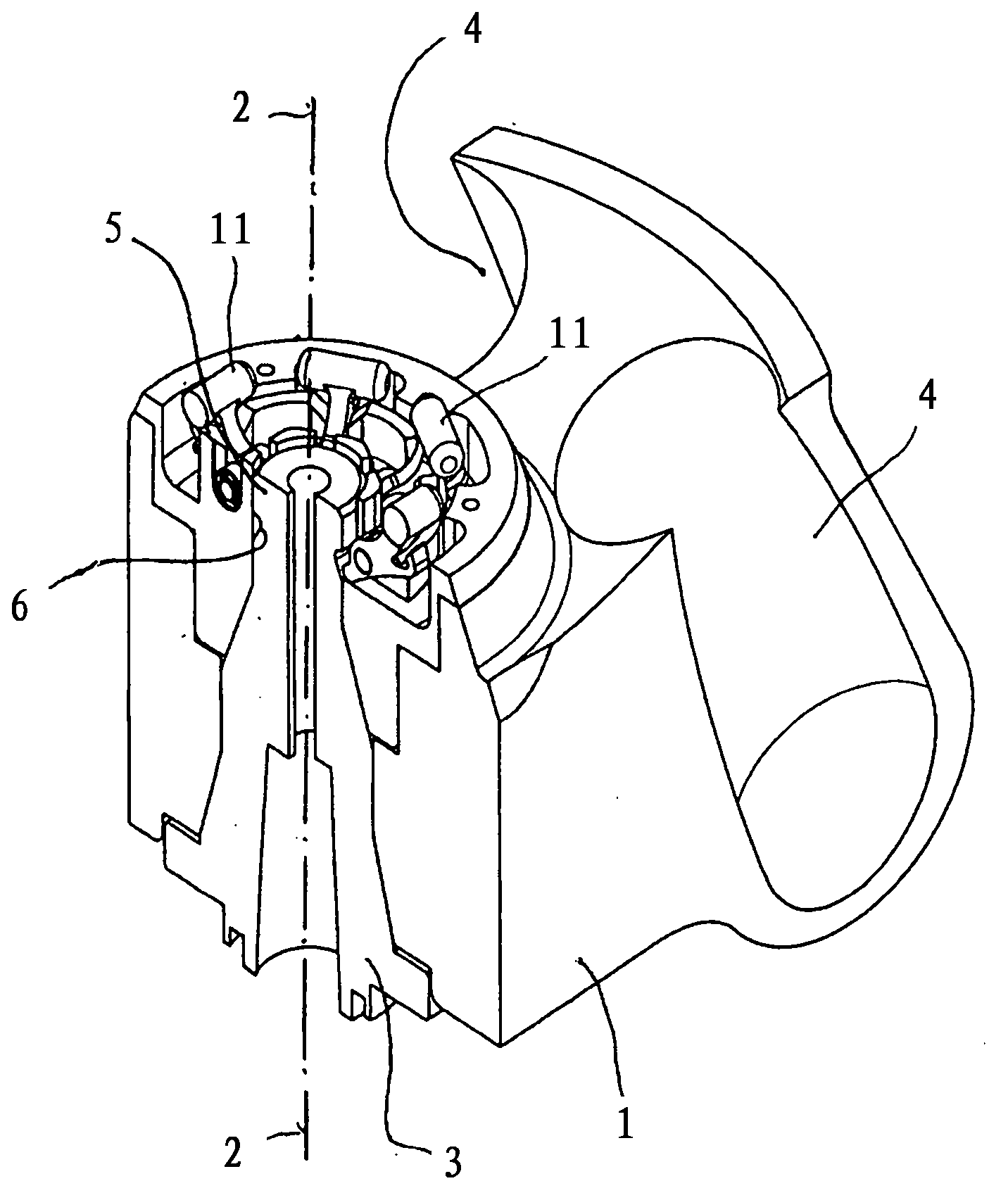
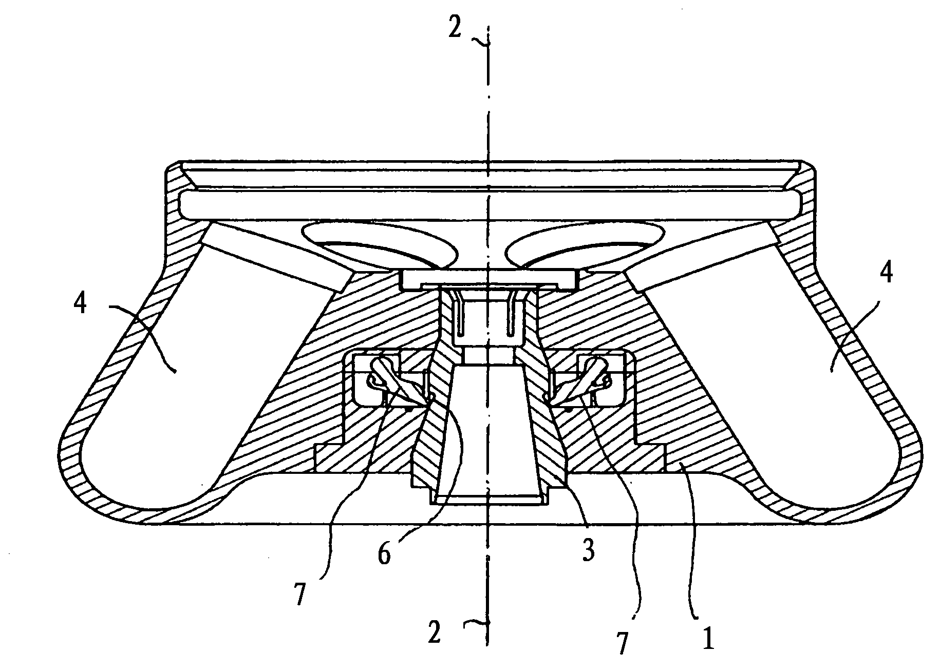
[0028] figure 1 and 2 In each case a rotor 1 of a laboratory centrifuge is shown, which can be slipped onto the upper end of a shaft 3 mounted rotatably about an axis 2 . The shaft 3 is connected to the drive in a manner not shown in the figures.

[0029] In a known manner, the rotor 1 is provided in the peripheral region with recesses 4 , which extend upward at an angle in the direction of the axis 2 and are respectively intended to receive containers for the mixture to be centrifuged.

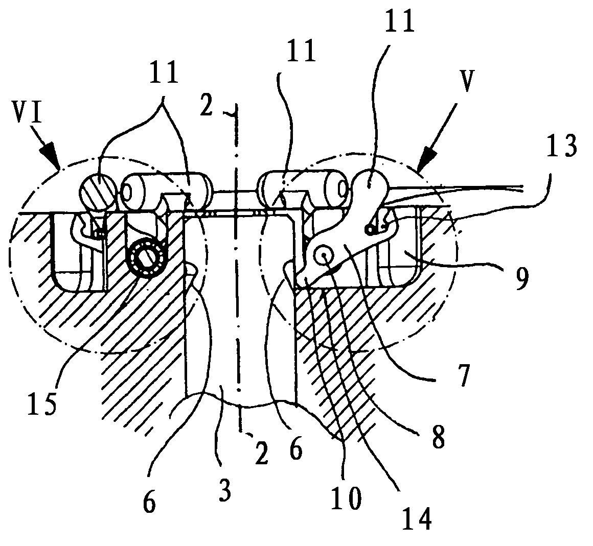
[0030] The shaft 3 has, on its upper end 5 for fitting the rotor 1 , a plurality of sections that enlarge conically in the axial direction from top to bottom, wherein the inner contour of the rotor 1 has sections adapted to the aforementioned sections. In particular, the outer contour of the shaft 3 has an annular groove 6 intended to cooperate with a locking system, which will also be described below, for ensuring a fixed fit of the rotor 1 in the socketed position, and Especially during ...


PUM


Abstract

The locking system, which is intended to axially secure the rotor (1), of a laboratory centrifuge, wherein said rotor can be placed onto a rotatably mounted shaft (3) that extends vertically, is characterized by an arrangement of a plurality of locking levers (7), which are each pivotably mounted about axes (8) extending perpendicularly to the shaft (3) between a locking position and an unlocking position in planes containing the axes (2), wherein said locking levers can each be automatically transferred from the unlocking position to the locking position and from the locking position to the unlocking position depending on rotational speed. The locking levers (7) are mounted on the rotor (1), and an annular groove (6) is provided on the shaft (3), said annular groove engaging with the locking levers (7) in the locking position, wherein the locking levers (7) are prestressed in the unlocking position. An advantage over the prior art is achieved, namely that the rotor can be both installed and removed without tools by merely placing the rotor onto or removing the rotor from the shaft (3), in each case depending on rotational speed.

Description

technical field [0001] The invention relates to a rotor support for a laboratory centrifuge according to the preamble of claim 1 . Background technique [0002] The rotor of such a laboratory centrifuge can be slipped from above in the housing onto the end of a shaft or a component fixedly connected to the shaft, which is connected to the centrifuge drive. The rotor is provided with an accommodating portion on the peripheral surface, and the accommodating portion is used for loading a container containing a substance to be centrifuged. In view of the high rotational speeds and the consequent risk of accidents, particular attention must be paid to a reliable and operationally safe fit of the rotor on the shaft. A hazard can arise here due to aerodynamic effects in the centrifuge housing which lift the rotor off the shaft, but also due to side impacts on the centrifuge housing. Due to the use of different rotors, the individual rotors are exchangeably connected to the shaft,...

Claims


Application Information

Patent Timeline
Patent Type & Authority Applications(China)
IPC IPC(8): B04B9/08B04B9/12
CPCB04B9/08B04B9/12B04B2009/085F16B21/16F16D43/16F16C35/00
Inventor B·彼得斯
Owner SIGMA LABORZENTRIFUGEN
Why Eureka
Try Eureka