Carding elements

A carding element, combing machine technology, applied in the direction of combing machines, fiber processing, textiles and paper, which can solve problems such as hindering the assembly process, and achieve the effect of simplifying maintenance and/or repair operations

Inactive Publication Date: 2015-11-25
STAEDTLER & UHL
View PDF18 Cites 0 Cited by
  • Summary
  • Abstract
  • Description
  • Claims
  • Application Information

AI Technical Summary

Problems solved by technology

Reduced mechanical retention between locking bar and base prevents simplified assembly process

Method used


Image

  • Carding elements
  • Carding elements
  • Carding elements

Examples


Embodiment Construction

[0049] exist Figures 1 to 10 The parts corresponding to each other are provided with the same reference numerals. Details of the embodiments described in more detail below may represent the invention per se or may be part of the subject-matter of the invention.

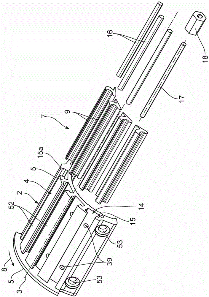
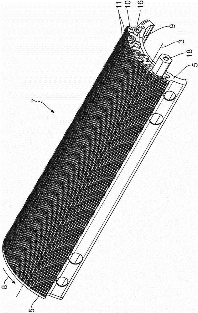
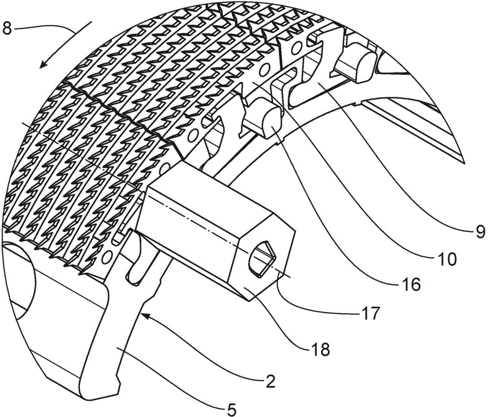
[0050] figure 1 with 2 The illustrated carding element 7 comprises a substantially part-cylindrical base body 2 with a central longitudinal axis 3 , an outer surface / peripheral surface 4 and two end surfaces 5 . The outer surface 4 includes portions of the outer surface 52 which are here interrupted along the periphery of the outer surface 4 to form multiples / segments / parts. figure 1 The rear end face 5 shown in (relative to the central longitudinal axis 3 ) constitutes a stop wall.

[0051] according to figure 1 The carding element 7 has a carding area of ​​90°. The combing elements 7 can be fastened on a drum / drum not shown. To this end, a plurality of perforations 53 are provided. The combing elements 7 fo...


PUM


Abstract

A combing element for a combing machine for combing textile fibres comprises a basic body (2) with a centre longitudinal axis (3), a circumferential surface (4) and two end surfaces (5), at least one catch (10) which is arranged on the circumferential surface (4) of the basic body (2), a profiled strip (9) for connecting the at least one catch (10) to the basic body (2), and a torsion rod (16) for locking and unlocking the profiled strip (9) on the basic body (2), wherein the profiled strip (9) is arranged in a receiving groove (14) of the basic body (2) and comprises a pivoting lever (19), by means of which the profiled strip (9) can be pivoted about a pivot axis (20) which is arranged parallel to the centre longitudinal axis (3), the torsion rod (16) is arranged in the receiving groove (14) such that it can be rotated about a rotational axis (17) which is arranged parallel to the centre longitudinal axis (3), the torsion rod (16) is accessible from outside the combing region, in particular from at least one of the end surfaces (5), the torsion rod (16) has a non-round cross section which is oriented perpendicularly with respect to the rotational axis (17), the torsion rod (16) is arranged on the pivoting lever (19) in such a way that, as a result of a rotation about the rotational axis (17), the torsion rod (16) can be displaced between a locked position for locking the profiled strip (9) on the basic body (2) and an unlocked position for unlocking the profiled strip (9) on the basic body (2).

Description

technical field [0001] The invention relates to a carding element of a combing machine for carding textile fibres. Background technique [0002] Combs used in combing machines are known from published prior applications in the form of circular combs, in which at least one cylinder holder is arranged on a base body. The cylinder pin holder engages the fibers to be carded. Combs with several cylinder seats along their entire circumference are called round combs. The effective carding area here can be, for example, 78°, 90°, 111°, 180° of the circumference of the outer body line of the comb. Circular combs are also known, in which the entire outer body line is occupied by a cylinder needle plate seat such as a colored needle, a needle strip, a saw-toothed steel wire segment, comb teeth or a saw-tooth stamping. These cylinder needle plate holders which are pre-assembled themselves are generally also called locking levers. [0003] The locking lever thus has a plurality of sa...

Claims


Application Information

Patent Timeline
Patent Type & Authority Patents(China)
IPC IPC(8): D01G19/10
CPCD01G19/105D01G19/10
Inventor E·多尔F·亨宁格
Owner STAEDTLER & UHL
Why Eureka
Try Eureka