Work machine peripheral monitoring device

A technology for working machines and monitoring devices is applied in the field of peripheral monitoring devices to achieve the effect of improving work efficiency

Active Publication Date: 2013-06-26
NIHON KENKI CO LTD
View PDF7 Cites 44 Cited by
  • Summary
  • Abstract
  • Description
  • Claims
  • Application Information

AI Technical Summary

Problems solved by technology

However, when a plurality of obstacles are displayed around the work machine, it is necessary to determine which obstacle is most likely to be in contact with
In this case, the operator himself has to make this judgment, and this judgment work will inevitably intervene between normal work (excavation work)

Method used


Image

  • Work machine peripheral monitoring device
  • Work machine peripheral monitoring device
  • Work machine peripheral monitoring device

Examples


Embodiment Construction

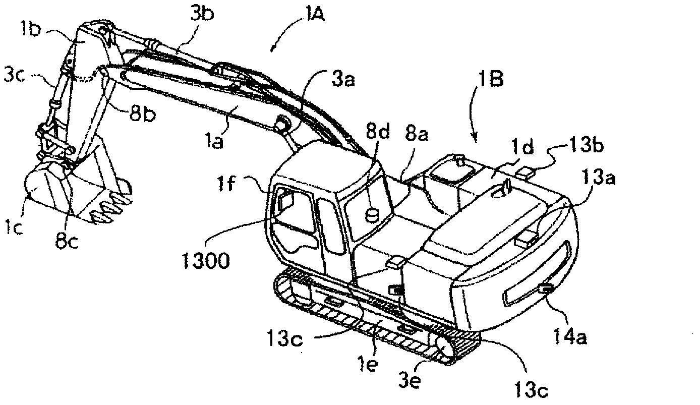
[0037] Hereinafter, embodiments of the present invention will be described with reference to the drawings. figure 1 It is an external view of a hydraulic excavator as an example of the working machine according to the embodiment of the present invention. The hydraulic excavator shown in this figure has: a multi-joint type front working device 1A composed of a boom 1a, an arm 1b, and a bucket 1c that rotate in the vertical direction; an upper rotating body 1b and a lower traveling body 1e The vehicle body 1B constituted, and the display device 1300 installed in the cab 1f.

[0038] A cab 1f is provided on the upper revolving body 1d. The base end of the boom 1a of the front working device 1A is supported by the front portion of the upper swing body 1d. The boom 1a, the arm 1b, the bucket 1c, the upper swing body 1d, and the lower running body 1e pass through the boom cylinder 3a, the arm cylinder 3b, the bucket cylinder 3c, the swing motor (not shown) and the left and right s...


PUM


Abstract

A work machine peripheral monitoring device comprises: an obstacle detection unit (400) for detecting an obstacle around the work machine using an image captured by a camera (13); a position calculation unit (500) for calculating the position of the detected obstacle; a hazard range calculation unit (700) for calculating a hazard range on the basis of the attitude and operation of the work machine; a determination unit (800) for determining whether or not the obstacle is present in the calculated hazard range; a hazard level setting unit (2000) for setting a contact hazard level with respect to the obstacle within the hazard range; an image production unit (600) for converting the camera image into a bird's-eye image centered on the work machine, and by adopting a bird's-eye view of the bird's-eye image from above the obstacle for which the contact hazard level has been set the highest by the hazard level setting unit, producing an image comprehensively including the work machine and the hazard range in the bird's-eye image; and a display device (1300) for displaying the produced image. Since this enables the position of the most hazardous obstacle with respect to the work machine to be grasped instantly by the operator, work efficiency by the work machine is improved.

Description

technical field [0001] The present invention relates to a peripheral monitoring device for monitoring obstacles around a work machine. Background technique [0002] Surrounding monitoring devices for working machines such as hydraulic excavators are used to monitor the surroundings of the working machine with a camera or the like to prevent contact with people and objects (obstacles) around the working machine during work. Among such techniques, as a technique for making it easier for the operator to grasp the positional relationship between the work machine and surrounding obstacles, there is a technique for superimposing and displaying on the display device an image showing the working state when the work is to be performed. Images that depict the posture of the machine and its working range, convert the image around the machine captured by the camera into a bird's-eye view image viewed from the viewpoint above the machine, and draw obstacles properly detected by a detecti...

Claims


Application Information

Patent Timeline
Patent Type & Authority Applications(China)
IPC IPC(8): E02F9/24
CPCE02F9/24E02F9/261E02F9/264G05B9/02F04B49/065H04N7/18
Inventor 小沼知惠子弓场龙石本英史
Owner NIHON KENKI CO LTD
Why Eureka
Try Eureka