
Cap tapping clamp

A fixture and cover technology, applied in the direction of clamping, manufacturing tools, supports, etc., can solve the problems of low efficiency, low positioning accuracy, complicated operation, etc., and achieve the effects of high rigidity, improved positioning accuracy, and quality assurance

Inactive Publication Date: 2013-07-03
PINGHU SHUNCHANG METAL PROD FACTORY
View PDF5 Cites 0 Cited by
  • Summary
  • Abstract
  • Description
  • Claims
  • Application Information

AI Technical Summary

Problems solved by technology

[0004] The present invention solves the problems of complex operation, low efficiency and low positioning accuracy of existing clamps

Method used


Image

  • Cap tapping clamp
  • Cap tapping clamp

Examples


Embodiment Construction

[0011] The present invention will be further described below in conjunction with drawings and embodiments.

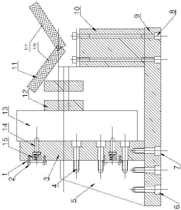
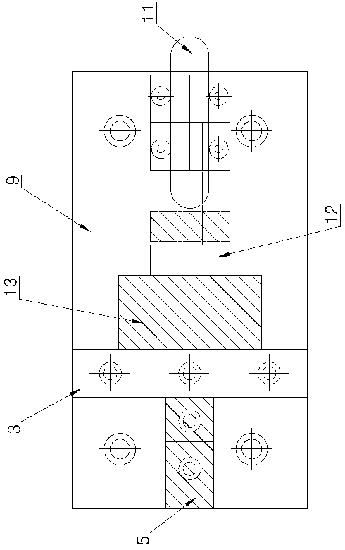
[0012] As shown in the figure, the present invention includes a base plate 9, a mounting plate 3, a quick clamp 11 and a spacer 10, the mounting plate 3 is fixed on the base plate 9 by bolts 7, the spacer 10 is installed on the base plate 9 by bolts 8, and the mounting plate 3 There is a certain distance between it and the spacer 10; one side of the installation plate 3 is provided with a reinforcing rib 5, and the other side is installed with a product 13. The bottom of the reinforcing rib 5 is fixed by the bolt 6 and the bottom plate 9, and the vertical side of the reinforcing rib 5 is fixed by the bolt 4 and the mounting plate 3 to ensure that the verticality between the mounting plate 3 and the bottom plate 9 is less than 0.05 mm; the product 13 is passed by the positioning pin 14 Vertically fixed on the mounting plate 3.

[0013] There is a spring 15 on the positi...


PUM


Abstract

The invention discloses a cap tapping clamp. The cap tapping clamp comprises a bottom plate, an installation plate, a quick clamp and a cushion plate, wherein the installation plate and the cushion plate are fixed on the bottom plate by a screw; a reinforcing rib is arranged at one side of the installation plate; a product is arranged at the other side of the installation plate; the product is fixed on the installation plate by a dowel pin; the quick clamp is arranged on the cushion plate; and the quick clamp can be moved and turned over on the cushion plate. Compared with the conventional clamp fixed by the bolt, the cap tapping clamp is high in installation efficiency, good in fixing effect, convenient in dismounting of the product and high in positioning precision.

Description

technical field [0001] The invention relates to the field of clamps, in particular to a cover tapping clamp. Background technique [0002] The structure of the existing tapping fixture is complicated, and it is troublesome to install and fix the product. It is necessary to install the bolts one by one, and then remove the bolts one by one after tapping the teeth, and finally disassemble the product. The use of such fixtures is complex in operation, low in efficiency, and low in positioning accuracy. Contents of the invention [0003] The purpose of the present invention is to provide a cover tapping jig. [0004] The invention solves the problems of complicated operation, low efficiency and low positioning accuracy of the existing clamps. [0005] The technical solution adopted by the present invention to solve its technical problems is: the present invention includes a base plate, a mounting plate, a quick clip and a spacer, and the mounting plate and the spacer are fi...

Claims


Application Information

Patent Timeline
Patent Type & Authority Applications(China)
IPC IPC(8): B23G1/44B23Q3/06
Inventor 丁建林胡中平叶强丁麓涵
Owner PINGHU SHUNCHANG METAL PROD FACTORY
Learn More