Base isolation non-contact limit system

A non-contact, foundation isolation technology, which is applied in the protection of building foundation isolation devices and the field of foundation isolation non-contact limit systems, can solve the problems of shock, large deformation, and large contact stiffness of the isolation layer. To achieve the effect of preventing damage

Inactive Publication Date: 2013-07-03
BEIJING UNIV OF TECH
View PDF5 Cites 16 Cited by
  • Summary
  • Abstract
  • Description
  • Claims
  • Application Information

AI Technical Summary

Problems solved by technology

The first two limit measures, due to the high contact stiffness during the collision, will bring impact to the shock-isolation layer, and when the impact is large, it will cause structural damage; the third measure, becau

Method used


Image

  • Base isolation non-contact limit system
  • Base isolation non-contact limit system

Examples


Embodiment 1

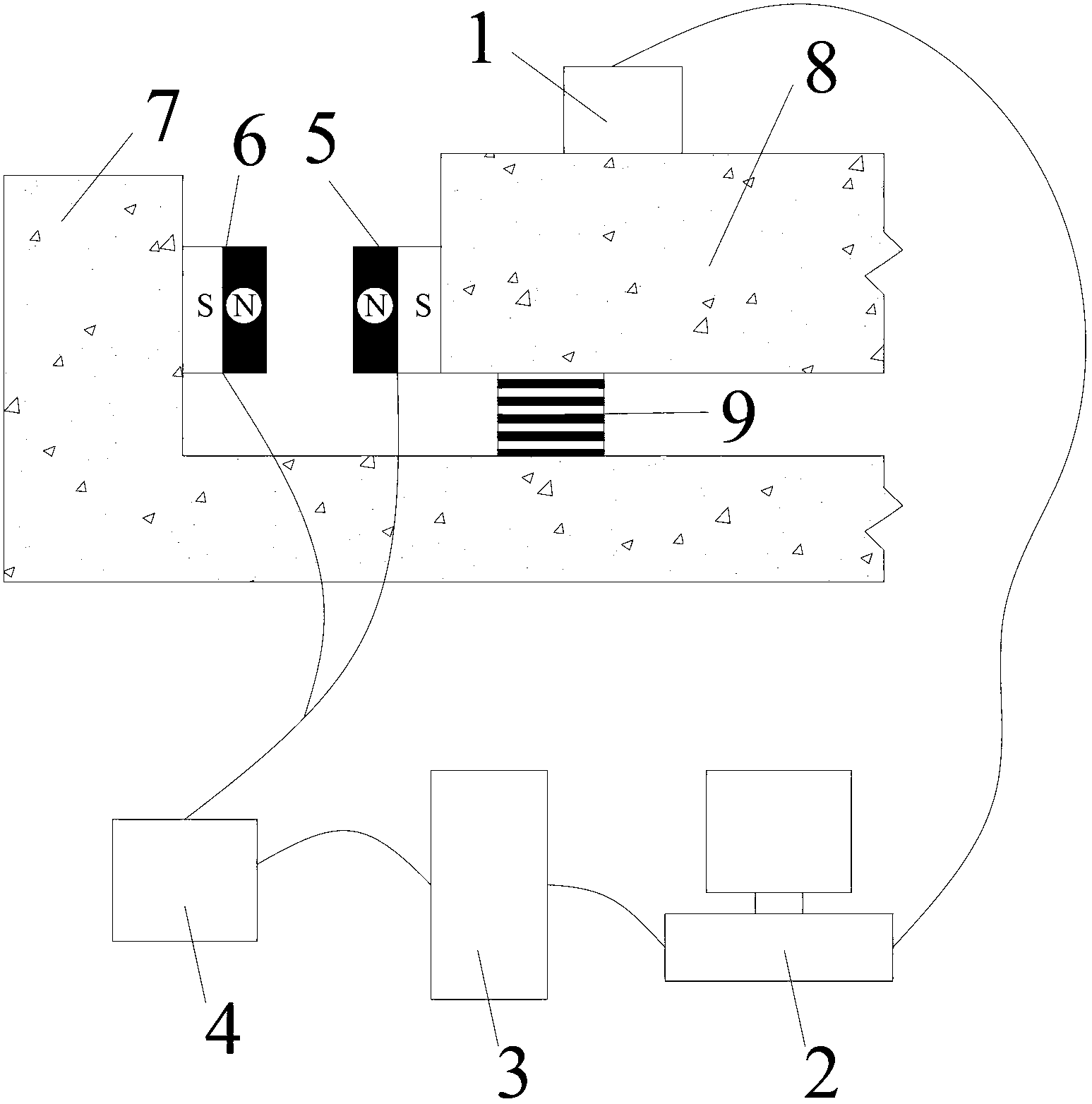
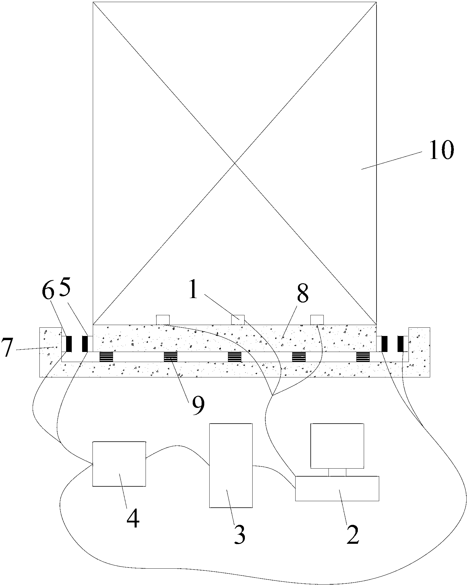
[0017] Such as Figure 1-2 As shown, the basic shock-isolation non-contact limit system of the present invention, its specific implementation is as follows:

[0018] For the rubber bearing isolation structure, around the upper floor 8 of the isolation layer, set the reaction support 7 connected with the foundation, install the limit magnet II6 on the reaction support 7, install the limit magnet I5 On the floor 8 on the upper part of the shock-isolation layer, the N poles or S poles of the two magnets are opposite, leaving a reserved distance between them. Both the limit magnet I5 and the limit magnet II6 are electromagnets. When the upper floor 8 of the shock-isolation floor moves sideways, the sensor 1 collects the signal, and after the analysis system 2 calculates, the controller 3 sends an instruction to the power supply system 4, and the power supply system 4 supplies the limit magnet I5 and the limit magnet II6. With a specific current, the limit magnet I5 and limit mag...

Embodiment 2

[0021] This embodiment is similar to Embodiment 1, except that both the limit magnet I5 and the limit magnet II6 are limited to permanent magnets, and the sensor 1, the analysis system 2, the controller 3 and the power supply system 4 are not required at this time.


PUM


Abstract

A base isolation non-contact limit system belongs to the technical field of shock reduction and shock isolation in an engineering structure, and includes a limit magnet I (5), a limit magnet II (6) and a counter force support (7), wherein the counter force support (7) is connected with a base; the limit magnet II (6) is anchored onto the counter force support (7); the limit magnet I (5) is anchored onto a shock isolation layer upper floor system(8); N poles or S poles of the limit magnet I (5) and the limit magnet II (6) are opposite; and distance is reserved between the limit magnet I (5) and the limit magnet II (6). According to the homo-polar repulsion principle of the magnet, counter force is generated between the magnets to limit and control displacement of a shock isolation layer within a safe range, so that damage to the shock isolation layer and other auxiliary devices can be avoided.

Description

technical field [0001] The invention relates to a base isolation non-contact limit system using the principle of magnet homosexual repulsion, which belongs to the field of engineering structure damping and isolation technology, and is mainly used for the protection of base isolation devices of buildings such as houses and bridges . Background technique [0002] There are two most commonly used forms of foundation isolation structure, one is rubber bearing isolation structure, and the other is sliding isolation structure. Due to its excellent performance in earthquakes, it is more and more widely used. When investigating the earthquake-isolated buildings after the earthquake, it was found that the earthquake-isolation layer collided with the foundation. Due to the irregularity of the seismic wave, the low-frequency part of the earthquake wave has the possibility of resonating with the structure, so that the earthquake-isolation layer The displacement exceeds the original des...

Claims


Application Information

Patent Timeline
IPC IPC(8): E02D31/08
Inventor 杜红凯闫维明韩淼
Owner BEIJING UNIV OF TECH
Why Eureka
Try Eureka