Mechanical seal structure of radial split groove end face with imitation bird wing fin groove

A kind of end face mechanical seal and mechanical seal technology, which is applied in the direction of engine seal, mechanical equipment, engine components, etc., can solve the problems that it is difficult to meet the operation requirements of mechanical seal, the opening ability of the end face cannot be adapted, and the dry gas seal is difficult to open quickly, etc., to achieve Large bearing capacity, atmospheric film stiffness, easy to open effect

Active Publication Date: 2016-06-22
ZHEJIANG UNIV OF TECH
View PDF12 Cites 0 Cited by
  • Summary
  • Abstract
  • Description
  • Claims
  • Application Information

AI Technical Summary

Problems solved by technology

However, these spiral groove dry gas seals still have problems such as poor start-stop characteristics under low-speed and low-pressure or low-speed and high-pressure conditions, insufficient air film rigidity, and the ability to open the end face cannot adapt to a wider operating range. In the process, it is difficult to open quickly, the stability of low-speed operation is not good, and the sealing end face is prone to dry grinding, which makes it difficult to meet the operation requirements of mechanical seals under high-parameter conditions such as high pressure.

Method used


Image

  • Mechanical seal structure of radial split groove end face with imitation bird wing fin groove
  • Mechanical seal structure of radial split groove end face with imitation bird wing fin groove
  • Mechanical seal structure of radial split groove end face with imitation bird wing fin groove

Examples


Embodiment 1

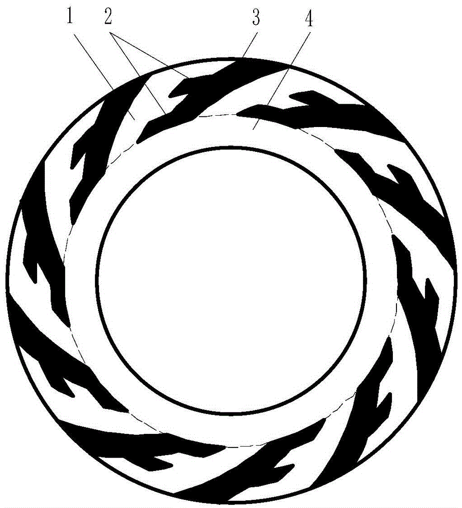
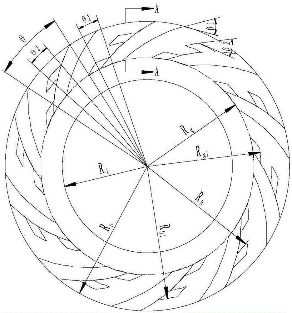
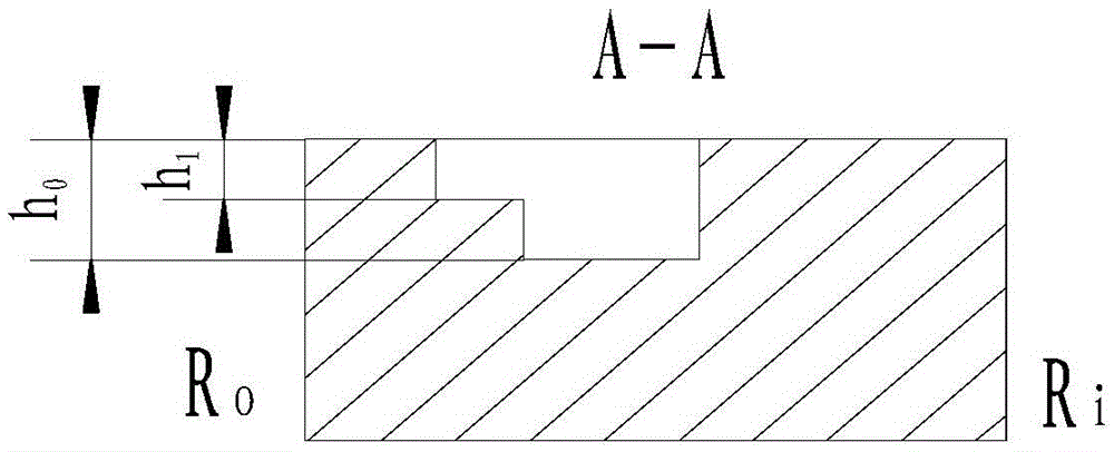
[0028] refer to figure 1 , figure 2 and image 3 , a radial split type groove end face mechanical seal structure imitating a bird wing groove, including two mechanical seal rings, namely a moving ring and a static ring, at least one mechanical seal ring in the moving ring or static ring is provided with a There are a plurality of radial diversion grooves imitating bird wing grooves distributed along the circumference of the sealing end surface. The radial diversion grooves imitating bird wing grooves are located on the high pressure side of the medium, namely upstream. The diversion groove includes a diversion groove 3 and more than two diversion grooves 2 with a structure similar to a bird's wing groove. extend. The ungrooved area between the radial diversion grooves imitating bird wing grooves is a sealing weir, and the annular zone formed by the ungrooved area in the circumferential direction of the end surface is a sealing dam, and the sealing dam is located on the low...

Embodiment 2

[0037] refer to Figure 4 , The difference between this embodiment and Embodiment 1 is that the shape of the shunt can be a triangle, a quadrilateral, a rhombus, or a trapezoid with a straight line, an arc line, or a spiral line on the side wall. One is the same.

Embodiment 3

[0039] refer to Figure 5 , the difference between this embodiment and the first embodiment lies in the ratio w of the circumferential arc length of the shunt groove 2 to the circumferential arc length of the sealing weir 1 corresponding to the drainage groove 3 1 / w=1, that is, the splitter groove 2 is a circumferential ring groove, and the rest of the structure and implementation are the same as in the first embodiment.


PUM


Abstract

The invention discloses a mechanical sealing structure for radial shunt type groove end faces of pinion-like grooves. The mechanical sealing structure comprises two mechanical sealing rings, namely a moving ring and a stationary ring, wherein a plurality of radial shunt type grooves of pinion-like grooves are distributed along peripheries and formed in the end surface of at least one mechanical sealing ring of the moving ring and the stationary ring; the radial shunt type grooves of pinion-like grooves are located at a high-pressure side of a medium, namely upstream; the radial shunt type grooves of pinion-like grooves comprise a drain groove and more than two shunt grooves adopting pinion-like groove structures; the drain groove is connected with the shunt grooves and is located on leeward sides of the shunt grooves; the shunt grooves are formed radially and stretch in a circumferential direction; uncut groove areas among the radial shunt type grooves of bird-wing-simulated grooves are sealing weirs; a ring belt which is formed in a circumferential uncut groove area on an end surface is a sealing dam; and the sealing dam is located on a low-pressure side of the end surface, namely downstream.

Description

technical field [0001] The invention relates to a gas end face mechanical seal structure of a rotary fluid machine, which is used for the gas seal of rotary shafts of various compressors, expanders, pumps, reaction kettles and other rotary machines. Background technique [0002] Due to its unique advantages, dry gas seals have been widely used in various high-speed rotating machinery, such as centrifugal compressors, expanders, fans, etc. The dry gas seal is to open various fluid dynamic and static pressure grooves on the sealing end surface. When the moving ring rotates, the gas medium is pumped into the sealing end surface by using the dynamic and static pressure effect of the groove, and the fluid medium entering the end surface is blocked from flowing at the root of the groove. Therefore, a certain opening force is generated and the end face is pushed away, so as to realize the non-contact operation of the dynamic and static rings. Among them, the most widely used end fa...

Claims


Application Information

Patent Timeline
Patent Type & Authority Patents(China)
IPC IPC(8): F16J15/16F16J15/40
Inventor 彭旭东江锦波白少先李纪云王玉明
Owner ZHEJIANG UNIV OF TECH
Why Eureka
Try Eureka