Mechanical sealing structure for radial shunt type groove end faces of pinion-like grooves
A sealing structure and mechanical seal technology, which is applied in the direction of engine seals, mechanical equipment, engine components, etc., can solve problems such as difficulty in meeting the operation requirements of mechanical seals, difficulty in opening dry gas seals quickly, and inability to adapt to the opening capacity of the end face, etc., to achieve load bearing Large capacity, atmospheric film stiffness, easy to open effect
- Summary
- Abstract
- Description
- Claims
- Application Information
AI Technical Summary
Problems solved by technology
Method used
Image
Examples
Embodiment 1
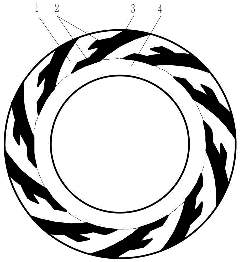
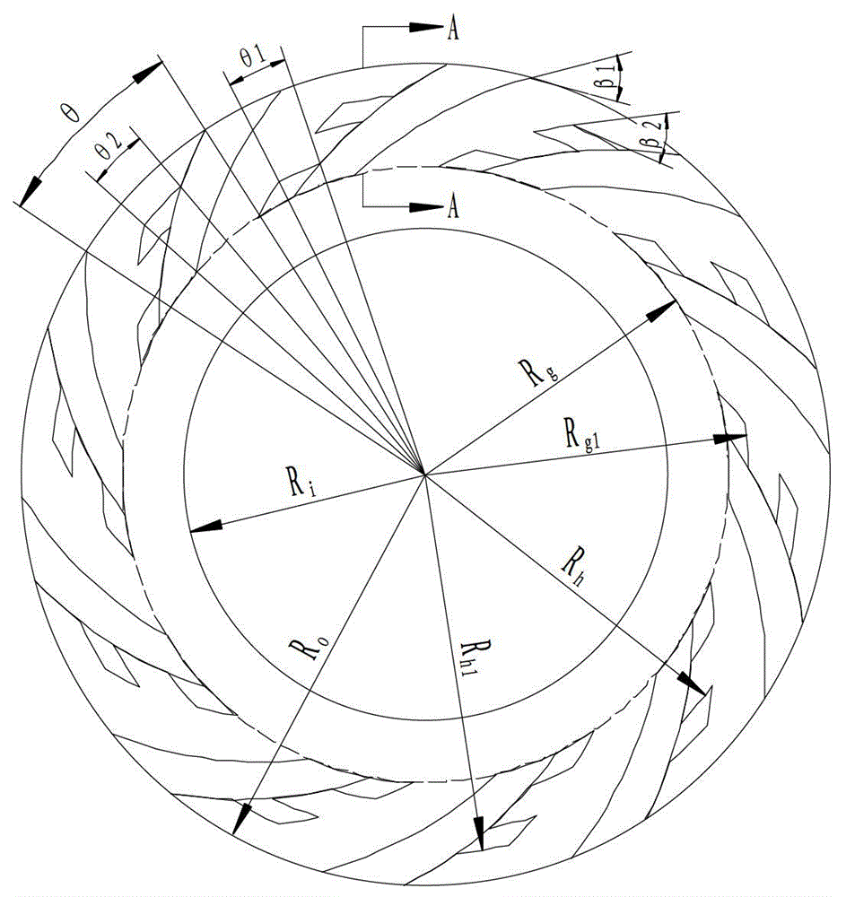
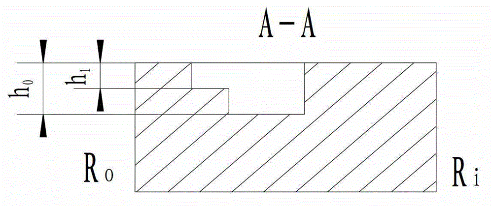
[0028] refer to figure 1 , figure 2 and image 3 , a radial split type groove end face seal imitating a bird wing groove, including two mechanical seals, namely a moving ring and a static ring, at least one mechanical seal ring in the moving ring or static ring is provided with a plurality of The radial diversion groove imitating the bird wing groove distributed along the circumference of the sealing end surface, the radial diversion groove imitating the bird wing groove is located on the high pressure side of the medium, that is, upstream, the radial diversion type groove imitating the bird wing The slot includes a drainage slot 3 and more than two diversion slots 2 with a structure similar to a bird's wing slot. The splitter slots 2 are located on the leeward side of the drainage slot 3, and the splitter slots are distributed radially and extend circumferentially. The ungrooved area between the radial diversion grooves imitating bird wing grooves is a sealing weir, and th...
Embodiment 2
[0037] refer to Figure 4 , The difference between this embodiment and Embodiment 1 is that the shape of the shunt can be a triangle, a quadrilateral, a rhombus, or a trapezoid with a straight line, an arc line, or a spiral line on the side wall. One is the same.
Embodiment 3
[0039] refer to Figure 5 , the difference between this embodiment and the first embodiment lies in the ratio w of the circumferential arc length of the shunt groove 2 to the circumferential arc length of the sealing weir 1 corresponding to the drainage groove 3 1 / w=1, that is, the splitter groove 2 is a circumferential ring groove, and the rest of the structure and implementation are the same as in the first embodiment.
PUM
| Property | Measurement | Unit |
|---|---|---|
| Depth | aaaaa | aaaaa |
| Depth | aaaaa | aaaaa |
Abstract
Description
Claims
Application Information
 - R&D
- Intellectual Property
- Life Sciences
- Materials
- Tech Scout
- Unparalleled Data Quality
- Higher Quality Content
- 60% Fewer Hallucinations
Browse by: Latest US Patents, China's latest patents, Technical Efficacy Thesaurus, Application Domain, Technology Topic, Popular Technical Reports.
© 2025 PatSnap. All rights reserved.Legal|Privacy policy|Modern Slavery Act Transparency Statement|Sitemap|About US| Contact US: help@patsnap.com


