
Antenna, manufacturing method of antenna, printed circuit board and communication terminal

A manufacturing method and antenna technology, applied to printed circuits, antenna supports/mounting devices, electrical components, etc., can solve the problems of increasing space requirements and design complexity, and achieve the effect of miniaturization

Active Publication Date: 2013-07-03
HUAWEI DEVICE CO LTD
View PDF6 Cites 9 Cited by
  • Summary
  • Abstract
  • Description
  • Claims
  • Application Information

AI Technical Summary

Problems solved by technology

Using this scheme, the bandwidth and efficiency of the antenna can basically meet the index requirements, but an additional balun (Balance) needs to be added to realize the impedance conversion and transmission mode conversion between the microstrip line and the coplanar waveguide, which increases the space requirement. and design complexity

Method used


Image

  • Antenna, manufacturing method of antenna, printed circuit board and communication terminal
  • Antenna, manufacturing method of antenna, printed circuit board and communication terminal
  • Antenna, manufacturing method of antenna, printed circuit board and communication terminal

Examples


Embodiment Construction

[0021] The technical solutions in the embodiments of the present invention will be clearly and completely described below in conjunction with the accompanying drawings in the embodiments of the present invention. Obviously, the described embodiments are only some, not all, embodiments of the present invention. Based on the embodiments of the present invention, all other embodiments obtained by persons of ordinary skill in the art without creative efforts fall within the protection scope of the present invention.

[0022] An embodiment of the present invention provides an antenna, which effectively utilizes a PCB metal body to achieve antenna performance.

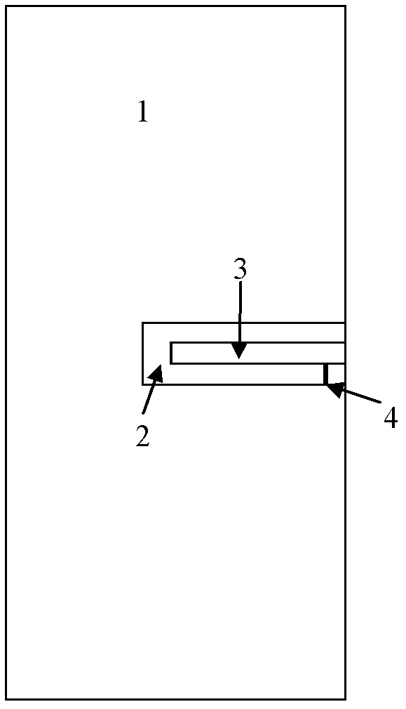
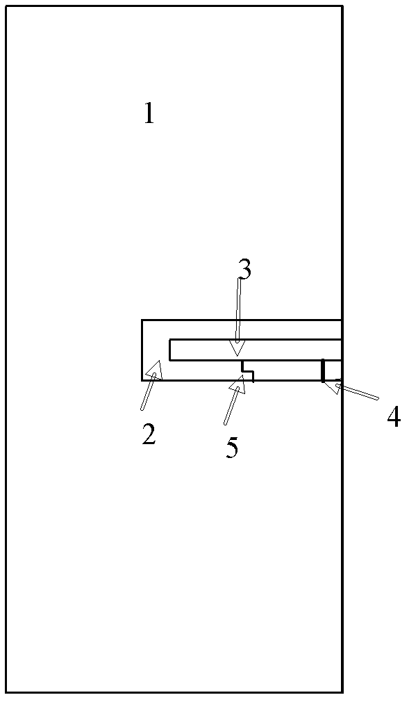
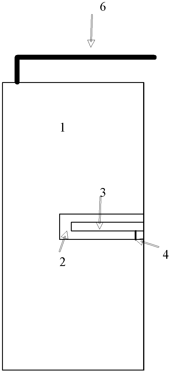
[0023] figure 1 It is a schematic diagram of an antenna structure according to an embodiment of the present invention. It can be seen that the antenna according to the embodiment of the present invention includes: a first radiator 1 and a second radiator 3 made of metal. The metal material here may be any metal material kn...


PUM


Abstract

An embodiment of the invention discloses an antenna, a manufacturing method of the antenna, a printed circuit board and a communication terminal. The antenna comprises a first radiating body, a second radiating body and feed points, wherein the first radiating body and the second radiating body are made of metal materials, and are separated with each other through a dielectric isolation portion, the first radiating body surrounds the second radiating body, and the feed points are in bridge joint at two ends of the dielectric isolation portion, and are connected with the first radiating body and the second radiating body. The antenna performance is achieved through electromagnetic coupling of the dielectric isolation portion between metal bodies, and therefore costs of communication equipment are reduced and space use rates of the printed circuit board are improved.

Description

technical field [0001] The present invention relates to the communication field, and more specifically relates to an antenna and a manufacturing method thereof, a printed circuit board and a communication terminal. Background technique [0002] With the continuous development and popularization of mobile wireless communications, the miniaturization of terminal equipment and the complexity of the printed circuit board (PCB) environment of products, the components used to transmit and receive wireless signals—antennas—are increasingly Miniaturization is urgently required. However, from the perspective of the existing antenna forms, due to the constraints of the product layout environment, the headroom space required for the realization of antenna bandwidth, efficiency, and out-of-roundness is becoming more and more difficult to meet, increasing product performance indicators to meet user requirements difficulty. Therefore, it is particularly urgent to make effective use of t...

Claims


Application Information

Patent Timeline
Patent Type & Authority Applications(China)
IPC IPC(8): H01Q1/36H01Q1/22H05K1/00
CPCH01Q1/38
Inventor 陈丽娜朱德进孙树辉周俭军
Owner HUAWEI DEVICE CO LTD
Learn More