Supercharge Your Innovation With Domain-Expert AI Agents!

PET blow moulding method for producing blow moulded PET containers and such a container

A container, protrusion technology, applied in the direction of containers, rigid containers, closures with auxiliary devices, etc.

Inactive Publication Date: 2013-07-03
UNILEVER NV
View PDF5 Cites 1 Cited by
  • Summary
  • Abstract
  • Description
  • Claims
  • Application Information

AI Technical Summary

Problems solved by technology

[0017] As mentioned above, the problem that arises in the conventional PET blow molding process is that it is difficult to form a defined shape in the product including "sharp" (ie, high curvature / low radius) features

Method used


Image

  • PET blow moulding method for producing blow moulded PET containers and such a container
  • PET blow moulding method for producing blow moulded PET containers and such a container
  • PET blow moulding method for producing blow moulded PET containers and such a container

Examples


Embodiment Construction

[0029]Other objects, features and advantages will appear from the following description of certain embodiments and drawings. These embodiments are described in sufficient detail to enable those skilled in the art to practice the disclosed systems and methods, and it is understood that other embodiments may be utilized without departing from the spirit and scope of the inventive system case, structural and logical changes can be made. In the description, the same or corresponding parts have the same or corresponding numbers. The exemplary embodiments shown should not be construed as limiting in any way, but merely as illustrations. Accordingly, the following detailed description is not to be taken in a limiting manner, and the scope of the inventive system is limited only by the appended claims. Moreover, for the sake of clarity, detailed descriptions of well-known devices, circuits, and methods are omitted so as not to obscure the description of the inventive system.

[003...


PUM

PropertyMeasurementUnit
lengthaaaaaaaaaa
lengthaaaaaaaaaa

Abstract

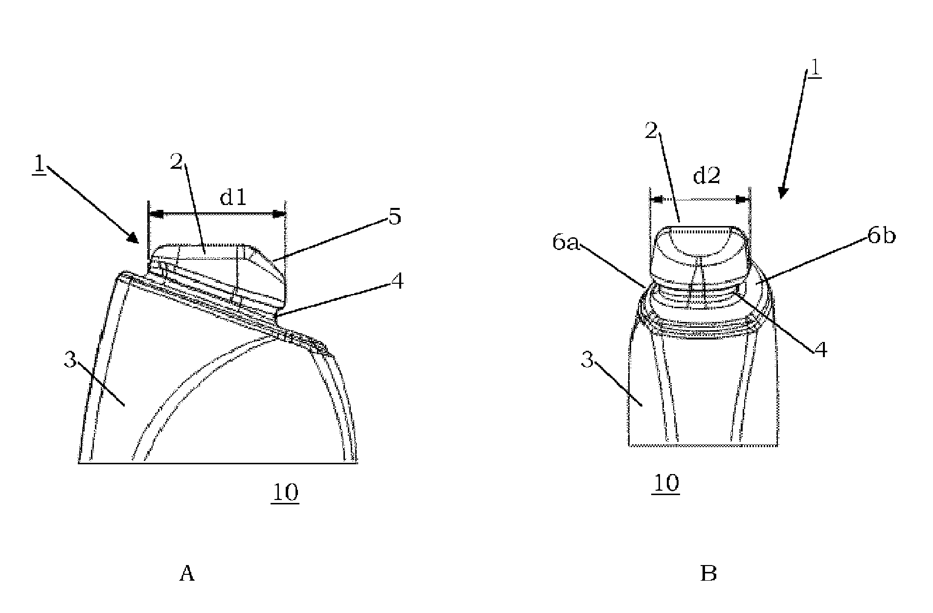
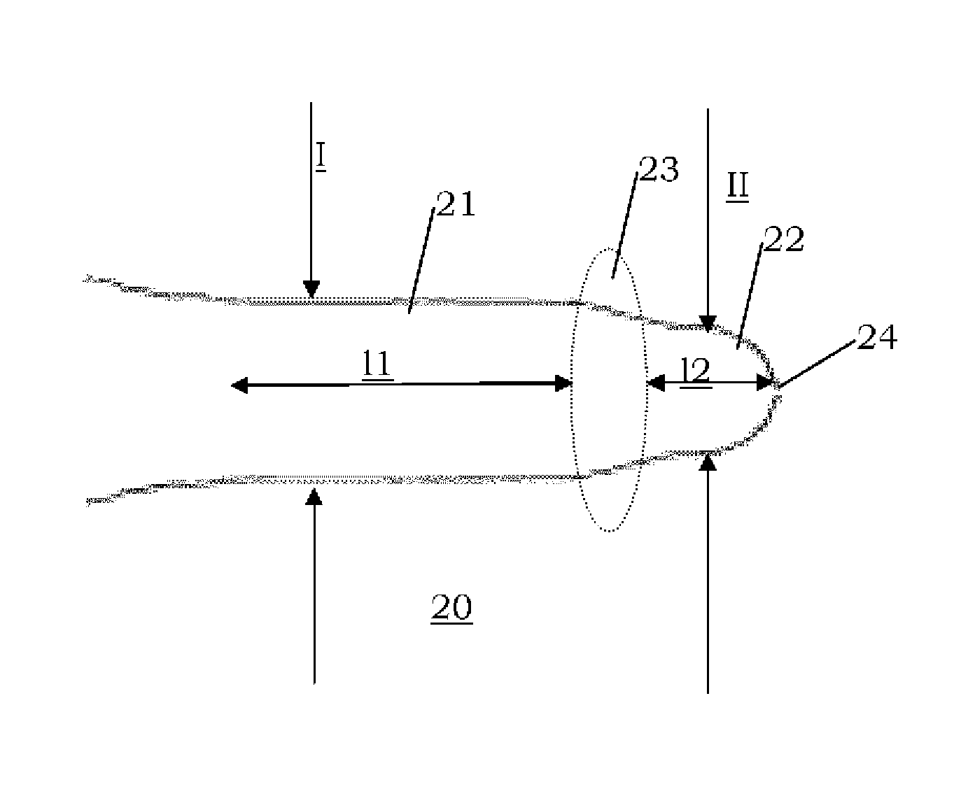
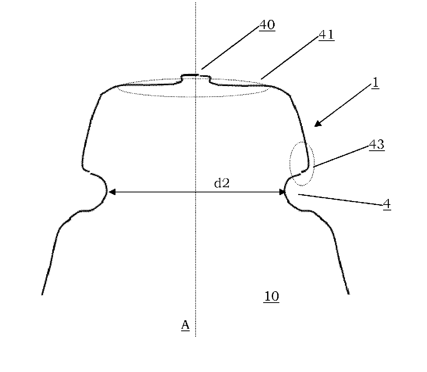
A PET blow moulding method is provided for producing a blow moulded PET container (10) suitable for snap fitting a base cap (60) and having an axial centre for enabling a blow molding process. PET preform (20,30) is inserted into a mould shaped to an inverse of the snap-fit PET container. Such a blow moulded PET container (10) is also disclosed. The PET preform is narrowed on a distal end side shaped for forming a knob portion (1) that is connected to a liquid compartment (3) of the PET container (10) via a neck portion (4), so as to form the knob having an inwards receding snap zone (43) formed by a curvature in the neck portion (4).

Description

technical field [0001] The present invention finds application generally in the field of PET blow molding for the manufacture of blow molded PET containers adapted to snap fit with bottom lids. The invention further relates to a blow molded PET container adapted to snap fit with a base cap and a base cap forming a stable connection therewith. Background technique [0002] Blow molded PET containers are containers capable of forming a snap-fit ​​connection with a second article (hereinafter referred to as "bottom cap"). To form this connection, both the container and the base cap are provided with a "snap fit" with a functional form definition that allows the "snap" process. The form definition may include, for example, a retracted snap-in area on the container which can be retained over a corresponding mating barrier on the bottom cap. A snap-fit ​​connection is formed when the respective snap-fit ​​portions are pushed together such that a threshold force related to the si...

Claims


Application Information

Patent Timeline
Patent Type & Authority Applications(China)
IPC IPC(8): B29C49/06B65D1/02B29B11/14B29B11/08
CPCB29B11/08B29B11/14B29C49/06B65D1/0246B65D47/0838B65D51/242B65D2251/105B29C49/071B29C2949/0715B29C2049/023B29C49/42B65D1/023
Inventor S.P.乔丹H.W.范埃斯博廷
Owner UNILEVER NV
Features
  • R&D
  • Intellectual Property
  • Life Sciences
  • Materials
  • Tech Scout
  • Unparalleled Data Quality
  • Higher Quality Content
  • 60% Fewer Hallucinations
Learn More