
Solar greenhouse bay window

A solar greenhouse and bay window technology, applied in the field of solar greenhouse bay windows, can solve the problems of insecurity, increased energy consumption of air conditioners, poor indoor thermal insulation, etc., so as to reduce the pressure of production and transportation, increase the content of oxygen, and improve the thermal insulation effect. Effect

Inactive Publication Date: 2013-07-10
CHONGQING UNIV
View PDF9 Cites 0 Cited by
  • Summary
  • Abstract
  • Description
  • Claims
  • Application Information

AI Technical Summary

Problems solved by technology

The first method can collect sunlight for heating and heat preservation in winter, but in summer, the indoor temperature is high because it cannot prevent sunlight from entering the room; the second method can block sunlight from entering the room in summer, although to a certain extent The indoor temperature is lowered, but this method only reflects most of the sunlight to prevent the sunlight from entering the room, and does not make effective use of solar energy. In addition, in winter, because the indoor cannot fully collect sunlight for heating, the Poor indoor insulation
[0005] The effect of vertical greening on shading and energy saving has been widely recognized. At present, it is more common for people to grow flowers and vegetables on balconies, but it is limited to low-rise and multi-storey buildings, while high-rise buildings are relatively windy and unsafe.
On the other hand, some windows in the building only provide light but no ventilation. In summer, a large amount of solar radiation heat penetrates, which increases the energy consumption of air conditioners.

Method used


Image

  • Solar greenhouse bay window
  • Solar greenhouse bay window
  • Solar greenhouse bay window

Examples


Embodiment Construction

[0031] The present invention will be described in further detail below in conjunction with the accompanying drawings and embodiments.

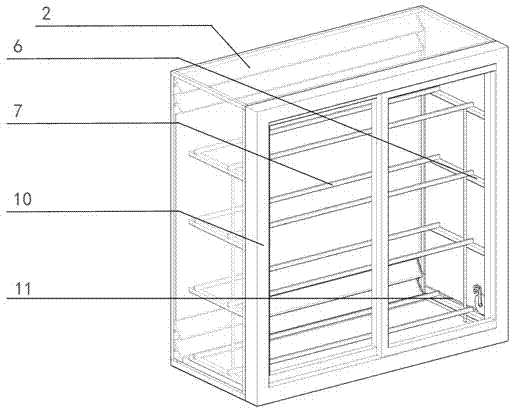
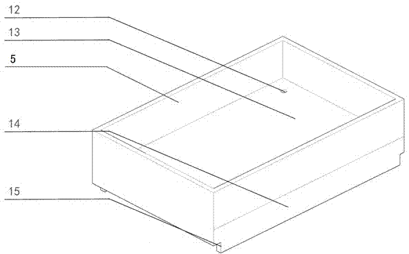
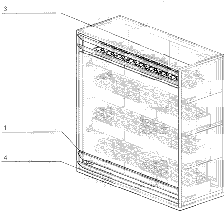
[0032] Example: Such as Figure 1-4 As shown, the bay window of the solar greenhouse includes a bay window frame 3, a glass fence arranged on the bay window frame 3, the glass fence forms a plant placement cavity, and the glass fence includes a top glass fence 2, a bottom plate 4, Left glass enclosure, right glass enclosure, be positioned at indoor front glass enclosure 10 and be positioned at outdoor rear glass enclosure; Bottom plate 4 can adopt glass material, or other materials in the prior art; Air-permeable glass louvers 1, the glass louvers 1 are arranged on the bay window frame 3 through a horizontally arranged rotating shaft; when the solar greenhouse bay windows are used in high-rise buildings, the glass louvers 1 are preferably arranged on the upper part of the vertical direction of the rear glass enclosure and / or Or the lower pa...


PUM


Abstract

The invention relates to a solar greenhouse bay window. The solar greenhouse bay window comprises a bay window frame, glass coamings and an elongated plant planting part, wherein the glass coamings are arranged on the bay window frame, and the elongated plant planting part is arranged in the plant accommodation cavity. The glass coamings form a plant accommodation cavity and comprise a top glass coaming body, a bottom plate, a left glass coaming body, a right glass coaming body, a front glass coaming body and a rear glass coaming body; the rear glass coaming body is provided with glass louvers for ventilation, and the glass louvers are arranged on the bay window frame through transversely-arranged rotary shafts; and a sliding groove is transversely arranged on the bottom plate, and the front glass coaming body is provided with a sliding portion with the bottom arranged in the sliding groove and capable of sliding back and forth in the sliding groove. Plants can be planted in the plant accommodation cavity in summer, and by the aid of the plants, a sun shading effect can be achieved, indoor air can be purified, and the oxygen content can be increased; and the plants in the plant accommodation cavity can be removed in winter, the solar greenhouse bay window can become a glasshouse, a heat insulation effect of double-layer hollow glass window can be achieved, sunlight can be transmitted directly, and the indoor insulating effect is improved.

Description

technical field [0001] The invention relates to the field of building bay windows, in particular to a solar greenhouse bay window. [0002] Background technique [0003] Oriel windows are generally divided into two types, one is stepped, and the other is completely floor-to-ceiling and integrated with the ground. Bay windows not only increase the lighting and ventilation functions of the apartment, but also add infinite architectural charm to the facade of the house, so most houses in recent years have bay windows. Unlike traditional flat windows, which have only one side of glass, bay windows have glass on three sides. The height of the window sill is also relatively low. The low window sill allows people to have a wider view and feel closer to nature. [0004] The oriel window increases the glass area of ​​the window opening, which increases the energy consumption of heating and air conditioning. As it is difficult to install external sun-shading devices for bay window...

Claims


Application Information

Patent Timeline
Patent Type & Authority Applications(China)
IPC IPC(8): E06B7/28E06B7/14
Inventor 郑星唐鸣放
Owner CHONGQING UNIV
Learn More