Panoramic vision system with synchronous shot parameter adjusting function

A technology of panoramic vision and lens parameters, applied in the camera body, optics, instruments, etc., can solve the problems of difficult information fusion, limited ability to collect panoramic field of view of rotation speed, different image brightness, focal length, and field of view, etc. Solve visual blind spots, overcome image fusion problems, and improve the effect of fusion

Active Publication Date: 2013-07-10
湖州清舟船舶科技有限公司
View PDF7 Cites 14 Cited by
  • Summary
  • Abstract
  • Description
  • Claims
  • Application Information

AI Technical Summary

Problems solved by technology

[0002] A single camera can only perform visual observation in a certain direction, which cannot meet the multi-directional simultaneous monitoring tasks in the field of video surveillance
The emergence of multi-camera image stitching technology meets the needs of multi-directional monitoring, but in dynamic target tracking, due to differences in camera parameters (focal length, focus, aperture) between multiple cameras, image brightness, focal length, and field of view are different. Therefore, image stitching and information fusion are difficult
The pan / tilt is a camera installation platform that can provide multi-angle observation. Through the pan / tilt, a camera can also be rotated 360 degrees to monitor the entire scene, but its rotation speed is limited and the ability to collect the entire panoramic field of view is limited, so it is impossible to observe multiple directions at the same time. Multiple moving targets, unable to track fast moving targets, and unable to give users an overall panoramic field of view perception

Method used


Image

  • Panoramic vision system with synchronous shot parameter adjusting function
  • Panoramic vision system with synchronous shot parameter adjusting function
  • Panoramic vision system with synchronous shot parameter adjusting function

Examples


Embodiment Construction

[0014] The present invention is described in more detail below in conjunction with accompanying drawing example:

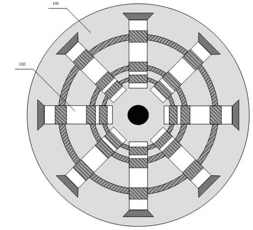
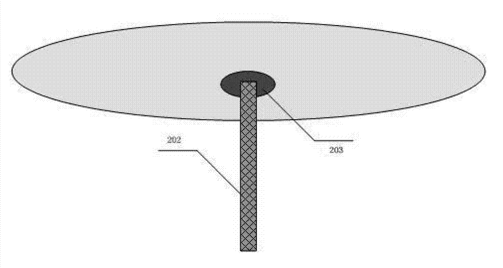
[0015] to combine Figure 1~5 , the present invention mainly uses a multi-camera mounting plate 101 device to install multiple cameras 102, and completes (focus, focal length, aperture) synchronous control. At the same time, the multi-camera mounting disc rotation device 203 is used to control the rotation of the camera mounting platform, so as to realize panoramic observation in a wide range without dead angles. The computer image acquisition and control system realizes the real-time acquisition and storage of pictures, as well as the control of camera lens parameters and the angle control of the multi-camera mounting plate [101].

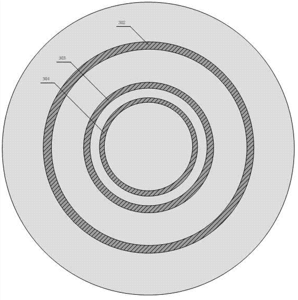
[0016] The multi-camera mounting plate 101 is a disc-shaped platform embedded with three gear rings, including a synchronous focus adjustment gear ring 302, a synchronous focus adjustment gear ring 303, and a synchronous aperture adj...


PUM


Abstract

The invention provides a panoramic vision system with a synchronous shot parameter adjusting function. The panoramic vision system with the synchronous shot parameter adjusting function comprises a camera, an installing disc, a rotating device and an upholder, the camera and the rotating device are installed on the installing disc, the upholder is connected with the rotating device, the rotating device controls the installing disc to rotate relative to the upholder, the installing disc is provided with a synchronous focus adjusting gear ring, a synchronous focal length adjusting gear ring and a synchronous aperture adjusting gear ring, the synchronous focus adjusting gear ring, the synchronous focal length adjusting gear ring and the synchronous aperture adjusting gear ring can rotate on the installing disc in a sliding mode, the camera is provided with a focus gear, a focal length gear and a aperture gear, and the synchronous focus adjusting gear ring of the installing disc, the synchronous focal length adjusting gear ring of the installing disc and the synchronous aperture adjusting gear ring of the installing disc respectively mesh with the focus gear of the camera, the focal length gear of the camera and the aperture gear of the camera. The panoramic vision system with the synchronous shot parameter adjusting function overcomes error accumulation caused by independent control of a camera parameter and guarantees that parameter errors of all cameras are within an acceptable range.

Description

technical field [0001] The invention relates to an observation system. Background technique [0002] A single camera can only perform visual observation in a certain direction, which cannot meet the multi-directional simultaneous monitoring tasks in the field of video surveillance. The emergence of multi-camera image stitching technology meets the needs of multi-directional monitoring, but in dynamic target tracking, due to differences in camera parameters (focal length, focus, aperture) between multiple cameras, image brightness, focal length, and field of view are different. Therefore, image stitching and information fusion are difficult points. The pan / tilt is a camera installation platform that can provide multi-angle observation. Through the pan / tilt, a camera can also be rotated 360 degrees to monitor the entire scene, but its rotation speed is limited and the ability to collect the entire panoramic field of view is limited, so it is impossible to observe multiple dir...

Claims


Application Information

Patent Timeline
Patent Type & Authority Applications(China)
IPC IPC(8): G03B37/04G03B17/56
Inventor 蔡成涛朱齐丹夏桂华梁小龙原新孟浩
Owner 湖州清舟船舶科技有限公司
Why Eureka
Try Eureka