Automatic dispenser

A glue dispenser and glue dispensing technology, which is applied to devices and coatings that apply liquid to the surface, can solve problems such as scrapping and contamination of products to be dispensed, and achieve the effects of reducing touch, saving manpower, and improving quality and quality.

Active Publication Date: 2013-07-17
SHENZHEN DINGJING TECH CO LTD
View PDF5 Cites 18 Cited by
  • Summary
  • Abstract
  • Description
  • Claims
  • Application Information

AI Technical Summary

Problems solved by technology

[0004] The main purpose of the present invention is to provide an automatic dispensing machine, aiming to solve the problem of contamination and scrapping of products to be dispensed caused by manual operation in existing semi-automatic dispensing machines

Method used


Image

  • Automatic dispenser
  • Automatic dispenser
  • Automatic dispenser

Examples


Embodiment Construction

[0047] It should be understood that the specific embodiments described here are only used to explain the present invention, not to limit the present invention.

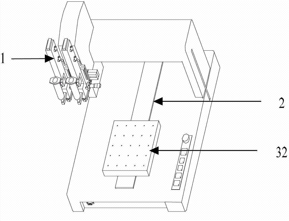
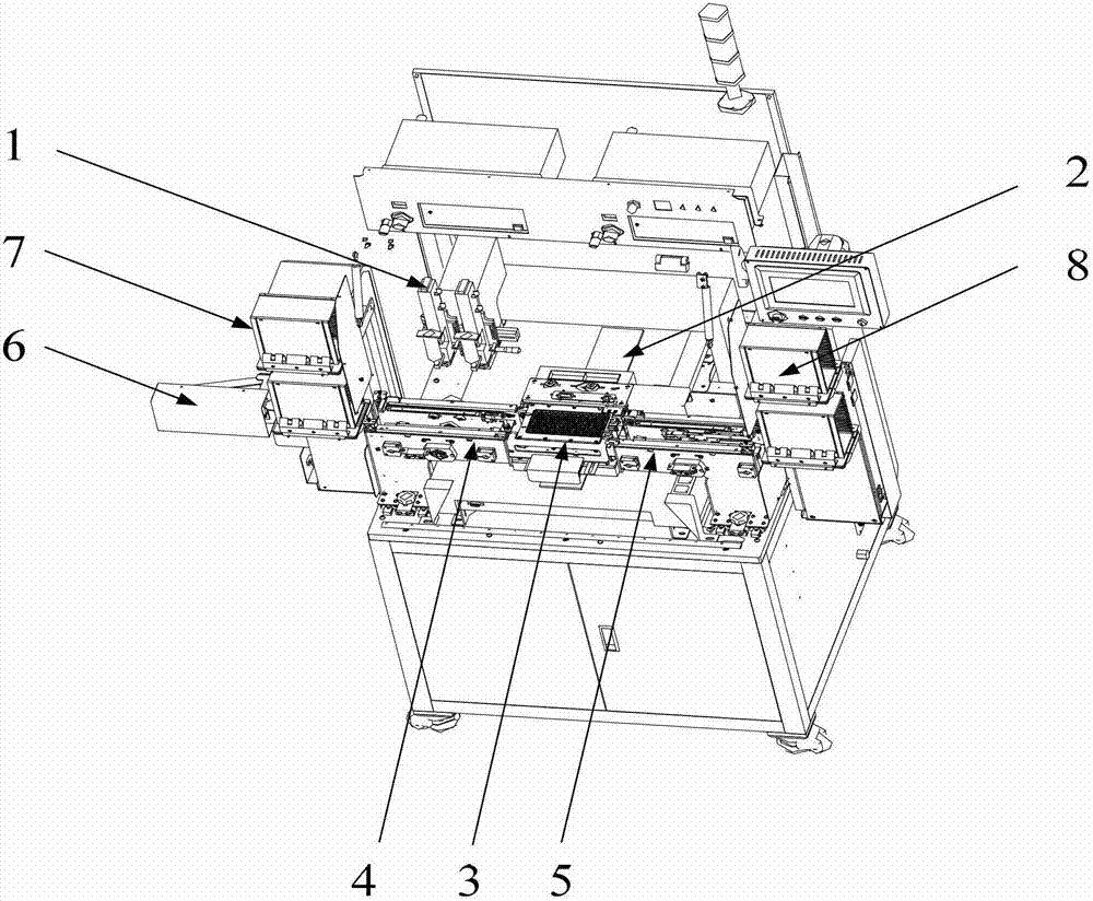
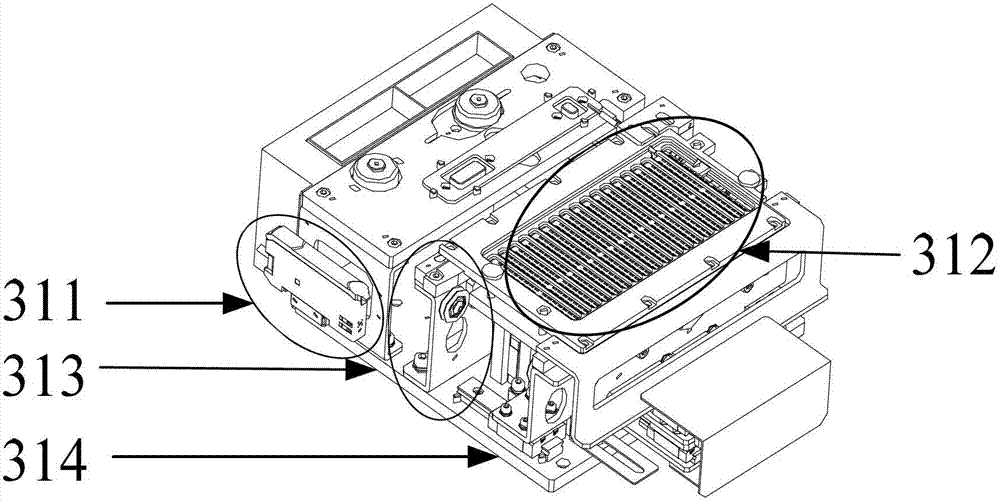
[0048] Please also refer to Figure 1 to Figure 8 As shown, among them, figure 1 It is a structural schematic diagram of a glue dispenser in the prior art; figure 2 It is a structural schematic diagram of an embodiment of an automatic dispensing machine of the present invention; image 3 is a structural schematic diagram of the dispensing device of the present invention; Figure 4 It is a schematic diagram of the decomposition structure of the dispensing device of the present invention; Figure 5 It is a schematic structural view of the feeding conveying device of the present invention; Figure 6 It is a structural schematic diagram of the assembly of the blanking conveying device and the blanking pushing device of the present invention; Figure 7 It is a schematic diagram of the front structure after the assemb...


PUM


Abstract

The invention provides an automatic dispenser comprising a dispensing operation platform, a guide rail, a feeding convey device, a discharging convey device and a dispensing convey device. The guide rail is arranged on the dispensing operation platform. The dispensing convey device moves along the guide rail to an output end of the feeding convey device to receive to-be-dispensed products conveyed by the feeding convey device and enters the dispensing operation platform along the guide rail to complete dispensing operation; and the dispensing convey device moves from the dispensing operation platform along the guide rail to an input end of the discharging convey device to convey dispensed products carried by the dispensing convey device to the discharging convey device. By the aid of the automatic dispenser, full automatic operations of feeding and discharging are realized, and working efficiency is high; and further, the process to place the to-be-dispensed products manually is avoided, manual touch by processing personnel on the products is reduced, and declared worthless of the to-be-dispensed products caused by false operation by the processing personnel is reduced, and quality of the dispensed products is improved.

Description

technical field [0001] The invention relates to the field of glue dispenser equipment structure, in particular to an automatic glue dispenser. Background technique [0002] At present, the commonly used dispensing machines are semi-automatic dispensing machines, such as figure 1 As shown, it includes a dispensing operation device 1, a dispensing console (not labeled in the figure), a guide rail 2 arranged in the direction of the vertical axis in the dispensing console, and a guide rail driving device 32 moving along the guide rail 2, wherein the guide rail driving device A dispensing device can be set on the 32. During specific operations, the product to be dispensed is manually added to the dispensing device, and then the product to be dispensed is entered into the dispensing operation platform along the guide rail 2 by the guide rail driving device 32, and cooperates with The dispensing operation device 1 completes the dispensing operation of the product to be dispensed. ...

Claims


Application Information

Patent Timeline
Patent Type & Authority Applications(China)
IPC IPC(8): B05C5/00B05C13/02
Inventor 陈勇杰颜志文
Owner SHENZHEN DINGJING TECH CO LTD
Why Eureka
Try Eureka