Method and device for measuring direct current magnetic bias error characteristics of current transformer

A technology of current transformers and error characteristics, applied in the field of high-voltage electrical measurement and inspection, to achieve traceability solutions, easy adjustment, and independent measurement systems

Active Publication Date: 2013-07-17
CHINA ELECTRIC POWER RES INST
View PDF9 Cites 21 Cited by
  • Summary
  • Abstract
  • Description
  • Claims
  • Application Information

AI Technical Summary

Problems solved by technology

According to the principle of equal ampere turns, the primary analog current is power frequency current and DC current respectively. Two independent current sources are convenient for amplitude control, and the measurement systems of power frequency current and DC current are independent of each other. Higher precision CT is used to measure The method and device for detecting the accuracy of the measured CT have not been found in published patents or literature works

Method used


Image

  • Method and device for measuring direct current magnetic bias error characteristics of current transformer
  • Method and device for measuring direct current magnetic bias error characteristics of current transformer
  • Method and device for measuring direct current magnetic bias error characteristics of current transformer

Examples


Embodiment 1

[0040] Embodiment 1, current comparison type error characteristic measurement and verification method and device:

[0041] Select standard power frequency AC current source, standard DC current source, standard current transformer CT according to the setting requirements N , as well as conventional transformer tester HEC-H, see attached Figure 4 , the standard current transformer CT N The output signal serves as a standard signal, CT N with the current transformer under test CT X The secondary output is connected into a differential circuit, and the standard current transformer CT N Only connected to the power frequency current source, the measured current transformer CT X At the same time through the power frequency current source and DC power supply, CT X with CT N The homonym end-butt, CT N with CT X The current difference between enters the transformer calibrator HEC difference measuring terminal K, CT N The other end is connected to the T of the transformer cali...

Embodiment 2

[0045] Embodiment 2, method and device for measuring and verifying voltage comparison error characteristics:

[0046] Select standard power frequency AC current source, standard DC current source, standard current transformer CT according to the setting requirements N , shunt R N1 , shunt R N1 and R o , Conventional dual-channel data acquisition card (the 5922 acquisition card of NI Company is used in this embodiment), and the analog quantity measurement part of the electronic transformer calibrator. See attached Figure 5 , the standard signal in the industrial frequency power supply passes through the standard current transformer CT N and subsequent connection of the shunt R N1 Convert standard current signal to standard voltage signal U a , the standard DC signal passes through the shunt R D Obtained, the power frequency signal and the DC signal are converted in the same proportion, and the standard current transformer together with the shunt R connected behind N2 T...


PUM


Abstract

The invention discloses a method and device for measuring direct current magnetic bias error characteristics of a current transformer. Current is simulated into a power frequency current source and a direct-current current source according to an equal ampere-turn principle, wherein the power frequency current source and the direct-current current source are independent, the standard computed tomography CT is used for detecting variation of error characteristics of the measured CT influenced by direct current magnetic bias, a method and device for measuring current comparison type error characteristics or voltage comparison type error characteristics is included, data can be compared in a whole process, and the method and device is suitable for measurement of error characteristics of during direct current magnetic bias of a straight through current transformer and also suitable for checking direct current magnetic bias error characteristics of current transformer coils made of different iron core materials.

Description

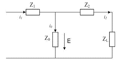
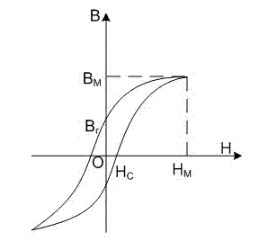
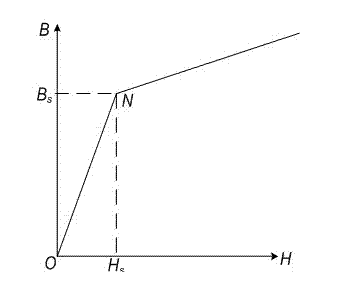
technical field [0001] The invention relates to a method and device for measuring the DC bias error characteristic of a current transformer, in particular to a method and device for verifying the error characteristic of the current transformer when the power frequency current of the primary circuit of the current transformer is simulated by the equal-ampere-turn principle. The method and device belong to the technical field of high-voltage electrical appliance measurement and inspection. Background technique [0002] The working principle of the traditional current transformer is the principle of electromagnetic induction. Generally, the primary circuit current of the current transformer is positive and negative symmetrical AC current, and the working flux density of the iron core in one cycle is also symmetrically distributed. When , the working magnetic density of the current transformer core will appear asymmetrical, resulting in asymmetrical hysteresis loops of the curre...

Claims


Application Information

Patent Timeline
Patent Type & Authority Applications(China)
IPC IPC(8): G01R35/02
Inventor 王欢王晓琪毛安澜吴士普汪本进冯宇费烨余春雨李璿王玲陈晓明
Owner CHINA ELECTRIC POWER RES INST
Why Eureka
Try Eureka