Packaging substrate and its manufacturing method

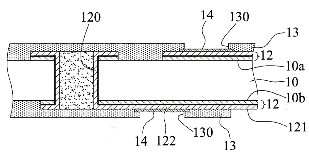
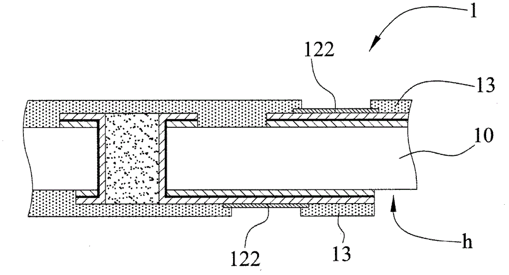
A technology for encapsulating substrates and substrates, applied in multilayer circuit manufacturing, semiconductor/solid-state device manufacturing, electrical components, etc., can solve problems such as abnormal structure of encapsulating colloid, delamination of surface treatment layer 14, and cracking of insulating protective layer 13, etc., to achieve Avoid delamination of the insulating protective layer, avoid product scrapping, and improve product reliability

Active Publication Date: 2016-01-20
UNIMICRON TECH CORP
View PDF3 Cites 0 Cited by
  • Summary
  • Abstract
  • Description
  • Claims
  • Application Information

AI Technical Summary

Problems solved by technology

[0008] However, in the existing manufacturing method of the packaging substrate 1, after removing the external portion 121, a depression h appears on the surface of the insulating protection layer 13. When a chip is placed on the insulating protection layer 13 in the subsequent process, the stress will be will concentrate around the depression h, causing the insulating protective layer 13 to crack around the depression h, thereby affecting the reliability of the product, and in severe cases, the product needs to be scrapped
[0009] In addition, when the encapsulant is formed in the subsequent process, the adhesive material is easy to flow into the depression h, so the flow direction of the adhesive material cannot be controlled, resulting in an abnormal phenomenon in the structure of the encapsulant
[0010] Furthermore, in the existing manufacturing method of the packaging substrate 1, the surface treatment layer 14 is formed first, and then the insulating protection layer 13 is formed, so the insulating protection layer 13 will cover part of the material of the surface treatment layer 14, resulting in the insulating protection layer 13 It is easy to delaminate at the surface treatment layer 14 due to poor combination with the surface treatment layer 14

Method used


Image

  • Packaging substrate and its manufacturing method
  • Packaging substrate and its manufacturing method
  • Packaging substrate and its manufacturing method

Examples


Embodiment Construction

[0048] Hereinafter, specific specific examples are used to illustrate the implementation of the present invention. Those skilled in the art can easily understand other advantages and effects of the present invention from the content disclosed in this specification.

[0049] It should be noted that the structure, ratio, size, etc. shown in the drawings in this specification are only used to match the content disclosed in the specification for the understanding and reading of those skilled in the art, and are not intended to limit the implementation of the present invention. Limited conditions, so it does not have technical significance. Any structural modification, proportional relationship change, or size adjustment should still fall under the present invention without affecting the effects and objectives that the present invention can produce. The disclosed technical content must be within the scope of coverage. At the same time, terms such as "上" and "一" cited in this specifica...


PUM


Abstract

The invention discloses a package substrate and a production method thereof. The production method of the package substrate includes forming a circuit layer which comprises an electrical contact pad and an external connection portion on the surface of a substrate body; forming a first insulating protective layer on the substrate body and exposing the electrical contact pad and the external connection portion; electrically connecting an electroplating device with the external connection portion to form a surface processing layer on the electrical contact pad through electroplating; removing the external connecting portion; and forming a second insulating protective layer on an exposed surface and the first insulating protective layer of the substrate body and exposing the electrical contact pad. Smoothness of surfaces of the insulating protective layers is maintained and reliability of products is improved due to the insulating protective layers which are formed through two times.

Description

Technical field [0001] The invention relates to a packaging substrate and a manufacturing method thereof, in particular to a packaging substrate for carrying semiconductor chips and a manufacturing method thereof. Background technique [0002] With the development of electronic products toward multi-function and high performance, different packaging types have been developed corresponding to semiconductor packaging structures, such as flip chip packaging (FlipChipPackage), wire bonding (WireBond), etc. In the current technology, the surface of the semiconductor integrated circuit (IC) chip is provided with an electronic pad, and the packaging substrate also has a corresponding electrical contact pad. Soldering bumps (inverted) can be used between the chip and the packaging substrate. Chip mounting type) or gold wire (wire bonding type) to electrically connect the chip to the packaging substrate. Generally, a surface treatment layer is formed on the electrical contact pads of the...

Claims


Application Information

Patent Timeline
Patent Type & Authority Patents(China)
IPC IPC(8): H01L21/48H05K3/46H01L23/498H05K1/02
Inventor 刘智文游志勋
Owner UNIMICRON TECH CORP
Why Eureka
Try Eureka