Apparatus for reading magnetic recording medium

A technology of magnetic recording medium and reading device, which is applied in the direction of induction recording carrier, cooperating device, instrument, etc., can solve the problems of unimplemented countermeasures and complicated structure, etc., and achieve the effect of preventing illegal acquisition.

Active Publication Date: 2013-07-17
HITACHI OMRON TERMINAL SOLUTIONS CORP
View PDF8 Cites 7 Cited by
  • Summary
  • Abstract
  • Description
  • Claims
  • Application Information

AI Technical Summary

Problems solved by technology

However, in this card reader, a signal conversion mechanism for converting the signal read by the head of the front head into a different signal is required, and the structure becomes complicated.
In addition, there is no countermeasure against type 1 theft, and there is a risk that data will be obtained illegally by an illegal reading device installed outside the card insertion slot.

Method used


Image

  • Apparatus for reading magnetic recording medium
  • Apparatus for reading magnetic recording medium
  • Apparatus for reading magnetic recording medium

Examples


Embodiment approach 1

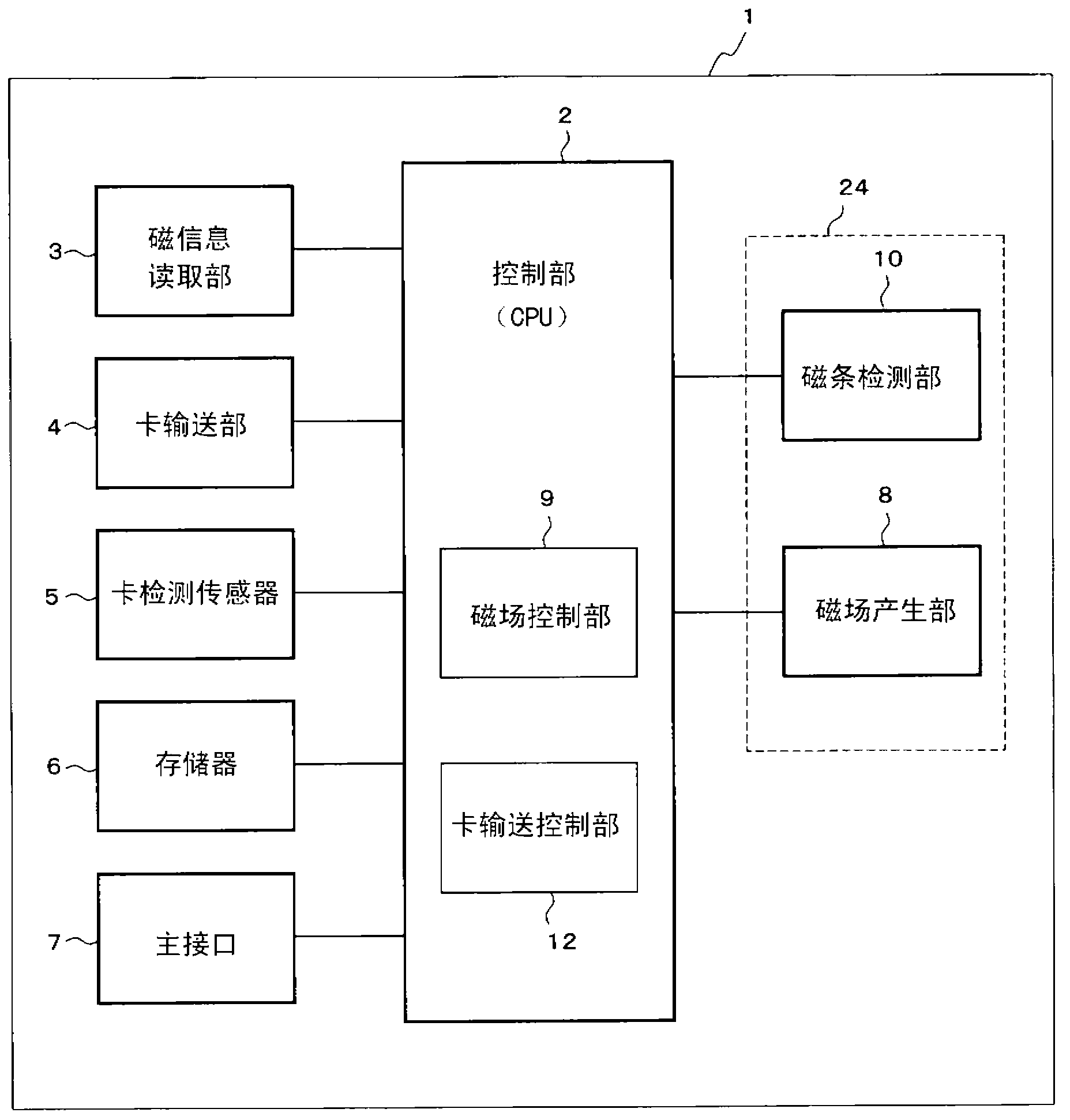
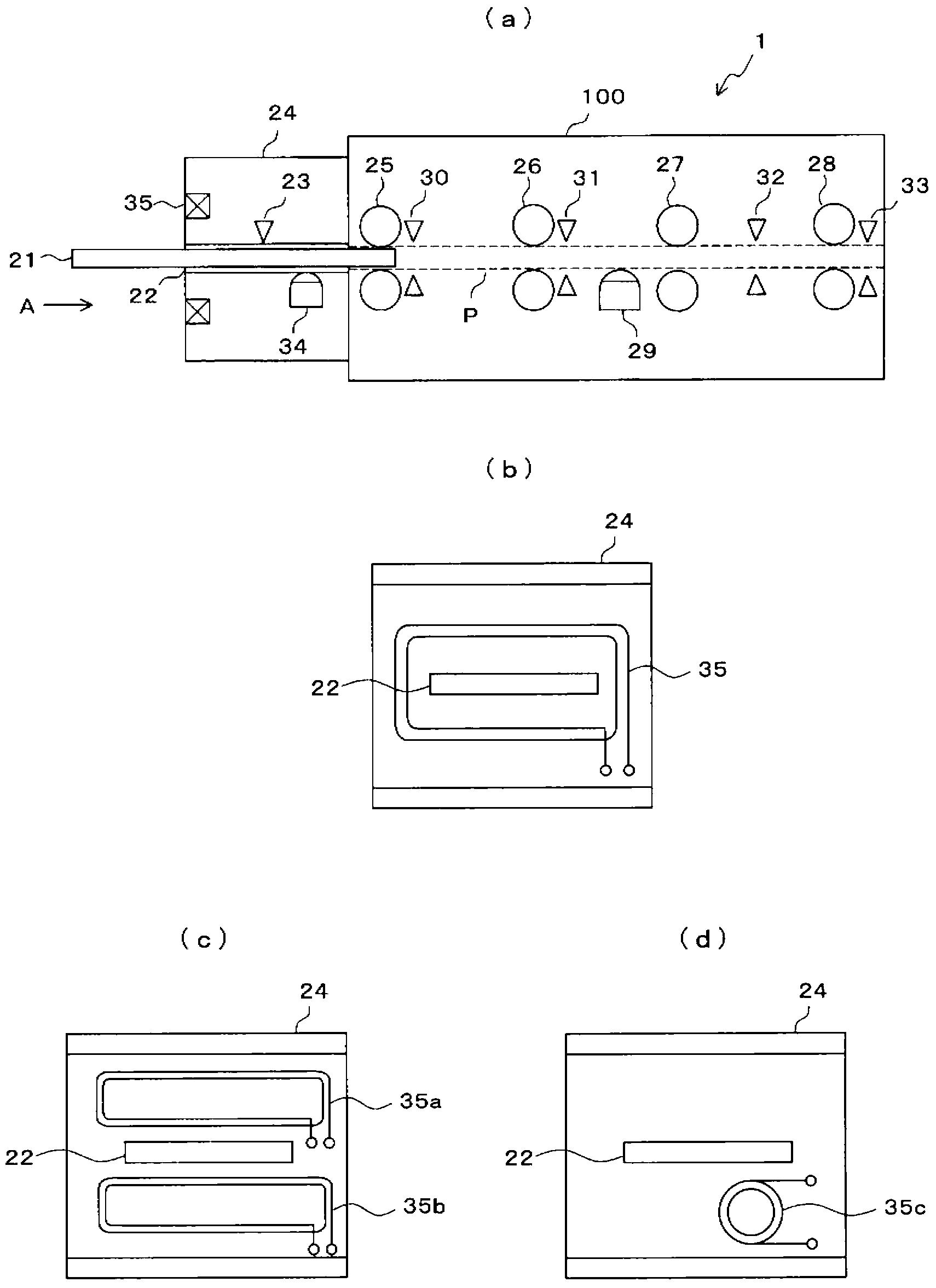
[0046] First, refer to figure 1 with figure 2 The structure of the card reader of Embodiment 1 is demonstrated.

[0047] Such as figure 1 As shown, in the present embodiment, the card reader 1 has: a control unit 2, including a CPU that controls the overall operation of the device; a magnetic information reading unit 3, that reads the magnetic data recorded in the magnetic card; a card delivery unit 4, that transports the magnetic card; Detecting sensor 5, detects magnetic card; Memory 6, stores the magnetic data read by magnetic information reading part 3; Main interface 7, is the connecting part with host device (such as ATM); Magnetic strip detecting part 10, detects the magnetic of magnetic card. a magnetic stripe; and a magnetic field generating unit 8 that generates a disturbing magnetic field for preventing reading of data recorded in the magnetic stripe.

[0048] The control unit 2 includes a magnetic field control unit 9 for controlling the magnetic field generati...

Embodiment approach 2

[0073] Next, Embodiment 2 of the present invention will be described. Among them, regarding the structure of the card reader in Embodiment 2, because it is related to figure 1 with figure 2 Same, description omitted. In addition, regarding the basic action of the card reader, it is also because of the Figure 4 with Figure 5 Same, description omitted.

[0074] Figure 7 yes Figure 4Timing diagram of the magnetic stripe detection performed in step S2 of the flowchart. In the above-mentioned first embodiment, the magnetic head 34 performs the reading operation only during the rest period X of the disturbance magnetic field, and in the second embodiment, the magnetic head 34 performs the reading operation during periods other than the rest period X.

[0075] Specifically, based on the control of the magnetic field control unit 9, such as Figure 7 The drive current shown in (a) flows through the loop antenna 35 . This drive current is the same as the drive current in ...

Embodiment approach 3

[0080] Next, Embodiment 3 of the present invention will be described. Among them, regarding the structure of the card reader in Embodiment 3, because it is related to figure 1 with figure 2 Same, description omitted. In addition, regarding the basic operation of the card reader, it is also because of the Figure 4 with Figure 5 Same, description omitted.

[0081] Figure 8 yes Figure 4 Timing diagram of the magnetic stripe detection performed in step S2 of the flowchart. In the first embodiment, the rest period X is provided in the disturbance magnetic field, but in the third embodiment, the frequency change period Y is provided in the disturbance magnetic field.

[0082] Specifically, based on the control of the magnetic field control unit 9, such as Figure 8 The drive current shown in (a) flows through the loop antenna 35 . This driving current is an AC signal having a predetermined vibration frequency, and there is a period Y during which the frequency changes ...


PUM


Abstract

A loop antenna (35) for generating a jamming magnetic field is provided near an insertion hole (22) into which a magnetic card (21) is to be inserted, and the jamming magnetic field is applied to a magnetic head (34). When the loop antenna (35) is generating a jamming magnetic field, and a magnetic card (21) is inserted into the insertion hole (22), a magnetic-stripe detection unit (10) outputs a detection signal with which just an evaluation of whether or not data is recorded within a magnetic stripe (21a) of the magnetic card (21) can be executed. With such a configuration, original data can be prevented from being obtained illegitimately, even when an illegitimate reading apparatus is connected to the magnetic-stripe detection unit (10) with lead wires.

Description

technical field [0001] The present invention relates to a device for reading data recorded on a magnetic recording medium, and more particularly to a magnetic recording medium reading device having a function of preventing illegal acquisition of data. Background technique [0002] A card reader for reading magnetic cards is mounted on transaction processing devices such as ATMs (Automated Teller Machines) and CDs (Cash Dispensers). In such a transaction processing device, a crime called theft has recently occurred. Theft is to illegally obtain data recorded on the magnetic stripe of the card when the magnetic card is inserted into the card reader. [0003] There are roughly two types of theft. One is to set an illegal reading device with a magnetic head to cover the card insertion port of the card reader that the ATM or CD has, and illegally obtain the data of the magnetic card inserted in the card reader through the magnetic head of the illegal reading device (hereinafter ...

Claims


Application Information

Patent Timeline
Patent Type & Authority Applications(China)
IPC IPC(8): G06K17/00G07D9/00G07F7/12
CPCG07F7/0873G07F19/2055G06K7/082G06K7/08G06K7/00G06K17/00
Inventor 木村智哉铃木唯道忠政明博铃木弘之
Owner HITACHI OMRON TERMINAL SOLUTIONS CORP
Why Eureka
Try Eureka