Escape system capable of gliding in deceleration

A technology of an escape device and a deceleration device, applied in the field of escape devices, can solve the problems of reducing friction, difficult to brake effectively, complex structure, etc., and achieve the effect of safe sliding process and simple mechanism

Inactive Publication Date: 2013-07-24
王勇
View PDF6 Cites 4 Cited by
  • Summary
  • Abstract
  • Description
  • Claims
  • Application Information

AI Technical Summary

Problems solved by technology

Its disadvantages are: [1] There are many groups of resistance guide columns and the structure is complex, and the two guide columns of each group are parallel to reduce the friction force of the rope on the resistance guide columns, which also requires multiple groups of resistance guide columns.
[2]The brake device is too complicated, and the friction plate, spring, and adjusting screw are redundant components
[3]The contact point between the swing rod and the rope is between the rotating shaft and the force position of the hand, resulting in inefficiency, and it is not easy to generate effective braking force when the weight of the human body slides down, that is, the braking effect is not timely, resulting in a fall wounded person who fell

Method used


Image

  • Escape system capable of gliding in deceleration
  • Escape system capable of gliding in deceleration
  • Escape system capable of gliding in deceleration

Examples


Embodiment 1

[0026] Embodiment 1, the escape device that can decelerate and slide down with the guide column fixed by the elongated hole

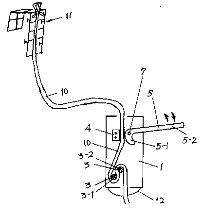
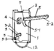
[0027] Such as figure 1 , 2 , comprising using two 8cm×15cm rectangular steel panels 1 of the same size to form a steel pipe body 2 with a thickness of 5cm, and the pipe body 2 is provided with a manual brake device and a deceleration device;

[0028] The manual brake device includes a fixed block 4 and an "L"-shaped brake handle 5, the fixed block 4 is fixed on the steel panel 1, and the short side 5-1 of the "L"-shaped brake handle 5 is adjacent to the fixed block 4 , the long side 5-2 of the "L" type brake handle 5 protrudes from the side of the pipe body 2, and the corner position between the short side 5-1 and the long side 5-2 is provided with a turning hole, and the turning hole is provided with a central axis 7 , the central axis 7 is fixedly connected with the panel 1, so that the "L" type brake handle 5 is rotationally connected with the pan...

Embodiment 2

[0033] Embodiment 2, the escape device that can decelerate and slide down with the guide column fixed by the bar-shaped slot

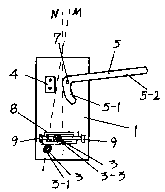
[0034] Such as figure 1 , 3 , as in Embodiment 1, the difference is the structure of the two guide columns of the deceleration device: among the two guide columns 3 of the deceleration device, one fixed guide column 3-1 is fixedly connected with the panel 1, and the other is position-adjustable Guide column 3-3; a bar-shaped card slot 8 is fixed on the panel 1, and the position can be adjusted. All are provided with adjusting screw 9 in. This is a structure that does not set elongated holes on the panel 1, but fixes a bar-shaped draw slot 8 on the panel 1 to adjust the distance between the two guide columns 3, that is, to adjust the spacing coefficient. The two adjustment studs 9 are in contact with the position-adjustable guide column 3-3 respectively, and the two adjustment studs 9 adjust and fix the position-adjustable guide column 3-3 at a posit...

Embodiment 3

[0035] Embodiment 3, the escape device that can decelerate and slide down is also adjusted by the relative position of the manual brake device and the deceleration device

[0036] As in embodiment 2, and the line M between the center point between the fixed block 4 and the short side 5-1 of the "L" type brake handle 5 and the fixed guide column 3-1 is 10 degrees from the centerline N of the pipe body 2 angle. This is also a structure that regulates the speed of the descent.


PUM


Abstract

The invention discloses an escape system capable of gliding in deceleration, which belongs to a device capable of controlling a gliding speed by means of a gliding process of a rope. The escape system comprises a tube body with two panels and an escape rope, wherein a manual brake device and a speed reducer are arranged in the tube body; the short side of an L-shaped brake handle of the manual brake device is adjacent to a fixed block, the long side of the L-shaped brake handle extends out of the side of the tube body, and the L-shaped brake handle is rotatably connected with the panels; and the speed reducer is composed of two guide pillars at a fixed interval up and down, and the spread ratio of the distance between the two guide pillars to the diameter of the escape rope is equal to 1.0: (0.8-1.1). The escape system disclosed by the invention has the advantages that the mechanism for controlling the gliding speed is simple, but the modes for controlling the sliding speed are various, and especially, the position relation of the manual brake device and the speed reducer can be used for controlling the gliding speed, so that the speed can be completely and freely controlled by people in the gliding process, the braking is timely, and the gliding process is safe.

Description

[0001] technical field [0002] The invention belongs to an escape device for sliding from a high place to a low place with the aid of a rope, in particular to a device for controlling the speed of the descent during the descent with the aid of a rope. Background technique [0003] Chinese patent CN201110090727.X "Controllable Safety Slow Down Device" discloses a slow down device for high-rise building fire escape or high-altitude operations, which consists of ropes, housings, brake wheels, friction plates, guide columns, springs and It is composed of regulating components; it is characterized in that the heavy object will not slide down freely when in use, and the person or the heavy object can be safely and slowly lowered by manipulating the pendulum. Its weak point has: [1] have many groups of resistance guide posts and complex structure, two guide posts of every group are parallel and have reduced the frictional force of rope on the resistance guide posts, also make it w...

Claims


Application Information

Patent Timeline
Patent Type & Authority Applications(China)
IPC IPC(8): A62B1/14
Inventor 王勇
Owner 王勇
Why Eureka
Try Eureka