
Adjustable pin distance large-size locating device with two pins on one side

A positioning device and adjustable technology, applied in workpiece clamping devices, manufacturing tools, etc., can solve problems such as affecting the normal operation of mechanical devices, damage to mechanical devices, and difficulty in ensuring the parallelism of two holes and the perpendicularity of holes and surfaces. , to achieve the effect of meeting work requirements, high strength, and solving positioning problems

Inactive Publication Date: 2013-07-24
NANJING AGRICULTURAL UNIVERSITY
View PDF5 Cites 2 Cited by
  • Summary
  • Abstract
  • Description
  • Claims
  • Application Information

AI Technical Summary

Problems solved by technology

However, when the size of the two positioning holes is very large, especially during the working process, when the positioning parts and the positioning device need to move together and are subjected to complex variable load external forces, the parallelism of the two positioning holes of the positioning parts, the hole and the surface The verticality will change, and it is difficult to guarantee the parallelism requirements of the two holes and the verticality requirements between the hole and the surface. At this time, if the above-mentioned common one-sided double-pin positioning device is used for positioning, it will affect the normal operation of the mechanical device. , will cause damage to the mechanical device in severe cases

Method used


Image

  • Adjustable pin distance large-size locating device with two pins on one side
  • Adjustable pin distance large-size locating device with two pins on one side
  • Adjustable pin distance large-size locating device with two pins on one side

Examples


Embodiment Construction

[0013] Below in conjunction with accompanying drawing and embodiment, the present invention will be further described:

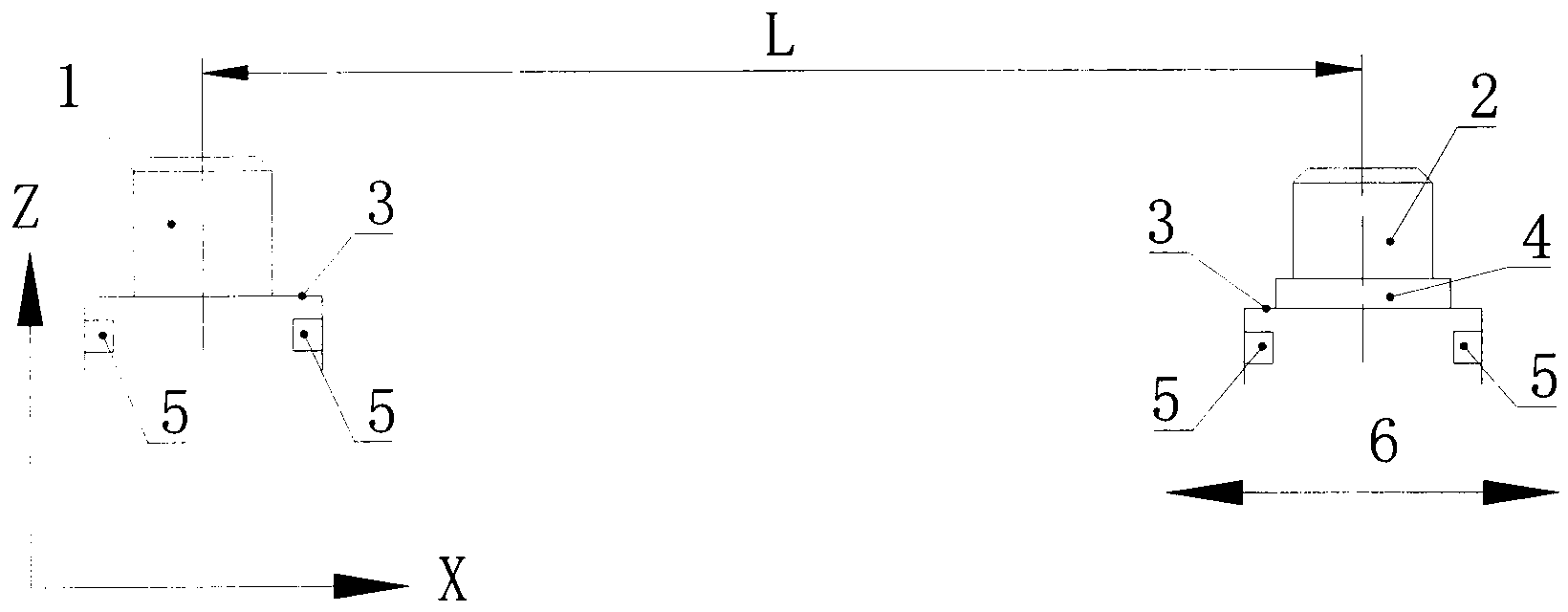
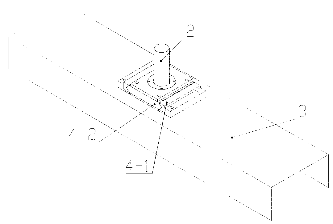
[0014] Such as Figure 1-Figure 2 As shown, the large-scale positioning device of the present invention is made up of fixed positioning pin 1, movable positioning pin 2, positioning block 3, moving pair 4, at least eight guide wheels 5, the positioning surfaces of left and right positioning blocks 3 are equal, and positioning block 3 At least two guide wheels 5 are fixedly connected to each side of the side plate, and the large-scale positioning device is installed in the guide groove of the large-scale mechanical guide rail through at least eight guide wheels 5, and the required movement is realized with the transmission mechanism; the fixed positioning pin 1 is floatingly installed in the positioning On the positioning surface of the block 3, the fixed part 4-1 of the moving pair 4 is fixedly connected with the positioning surface of the positioning block ...


PUM


Abstract

The invention discloses an adjustable pin distance large-size locating device with two pins on one side and belongs to the technical field of mechanical equipment. The adjustable pin distance large-size locating device with the two pins on one side is composed of a fixing locating pin, a movable locating pin, a locating block, a sliding pair and at least eight guide wheels. The large-size locating device is installed in a guide rail guiding groove of large machinery through the at least eight guide wheels, and the needed motion is achieved along with a transmission mechanism. The adjustable pin distance large-size locating device with the two pins on one side is characterized in that at least two guide wheels are fixedly connected at each edge of the inner side of a side plate of the locating block, the fixing locating pin is installed on a locating face of the locating block in a floating mode, the sliding pair is fixedly connected with the locating face of the locating block, the movable locating pin is installed on the sliding pair in a floating mode, and the movable locating pin can be driven to move through the sliding pair to achieve adjusting the center distance between the two locating pins. Edges of the locating pins in the adjustable pin distance large-size locating device do not need to be cut, and the adjustable pin distance large-size locating device with the two pins on one side is high in intensity, capable of solving the locating problems of large-size stressed parts, capable of changing along with poses of center lines of two locating holes in the working process of the large-size stressed parts and meeting work requirements of the large-size stressed parts.

Description

technical field [0001] The invention relates to a positioning device, in particular to a positioning device applied to large-scale force-bearing components. It belongs to the technical field of mechanical equipment. Background technique [0002] The combined positioning of double pins on one side is a common positioning method for box-type parts, which can realize the complete positioning of box-type parts. In order to prevent over-positioning, the usual method is to change the second cylindrical pin to a chamfered pin structure, the cylindrical pin, the chamfered pin and the positioning surface are fixedly connected, and the center distance between the two pins is fixed. This kind of one side-cylindrical pin-cutting pin structure usually has relatively high requirements on the parallelism of the two positioning holes of the positioning part and the perpendicularity between the hole and the surface, and the force on the cutting pin is very small during the working process. ...

Claims


Application Information

Patent Timeline
IPC IPC(8): B25B11/00
Inventor 仲高艳吴玥彤肖茂华徐秀英
Owner NANJING AGRICULTURAL UNIVERSITY
Learn More