
Screening device for railway ballasts

A screening device and ballast technology, applied in the directions of roads, tracks, ballast layers, etc., can solve the problems of low screening efficiency and achieve a wide range of applications.

Active Publication Date: 2013-07-24
GEMAC ENG MACHINERY +1
View PDF5 Cites 0 Cited by
  • Summary
  • Abstract
  • Description
  • Claims
  • Application Information

AI Technical Summary

Problems solved by technology

[0003] The purpose of the present invention is to overcome the deficiency of low screening efficiency in the prior art and provide a ballast screening device which utilizes two vibrating screens arranged in the same direction to realize high-efficiency ballast screening, and can clean the cleaned road after screening Ballast, under-sieve soil and waste ballast are transported separately

Method used


Image

  • Screening device for railway ballasts
  • Screening device for railway ballasts
  • Screening device for railway ballasts

Examples


Embodiment Construction

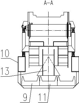
[0022] figure 1 , figure 2 Among them, the present invention includes a frame 10 with a side beam with a low middle convex structure at both ends, and the left and right ends of the frame 10 fall on two bogies 8, and the frame 10 and the bogies 8 are provided with a leveling cylinder 7.

[0023] The ballast conveying device A2 and the ballast conveying device B4 are located at the top, the first vibrating screen 5 and the second vibrating screen 6 and the first ballast hopper 12 arranged at the outlet of the first vibrating screen 5 and the second vibrating screen 6 are discharged The second ballast bucket 13 arranged at the mouth is located in the middle, the clean ballast conveying device 9 and the waste ballast conveying device 11 are located at the bottom, the swing conveying device 1 is at the left end of the frame 10, and below the mixed ballast conveying device A2. Above-mentioned parts all take root and are fixed on the frame 10. The discharge port of the ballast co...


PUM


Abstract

The invention relates to a screening device for railway ballasts, which comprises a rack, a first vibrating screen, a second vibrating screen, a mixed ballast conveyor A, a mixed ballast conveyor B, a cleaning ballast conveyor, a waste ballast conveyor, a first ballast separating bucket, a second ballast separating bucket and a swinging conveyor, wherein the first vibrating screen and the second vibrating screen are arranged on the rack in the same direction; the mixed ballast conveyor A and the mixed ballast conveyor B are arranged above the first vibrating screen and the second vibrating screen to form a railway ballast feeding system; and the cleaning ballast conveyor and the waste ballast conveyor are arranged below the first vibrating screen and the second vibrating screen. According to the screening device for the railway ballasts, which is disclosed by the invention, the double screens are arranged in the same direction in a limited space so that the railway ballasts are screened efficiently and the separated railway ballasts are respectively conveyed; and through a leveling oil cylinder connected between the rack and a bogie, the vibrating screens can be leveled in a screening process of railway curve ballasts, the requirement of operation on a curve is met, and the application range is wide.

Description

technical field [0001] The invention relates to a railway line maintenance machine, in particular to a device for screening track ballast. Background technique [0002] For the existing ballast cleaning machines, most of them are single vibrating screens with low screening efficiency, and the existing double screens are arranged in reverse, which cannot completely ensure that the ballast feeding direction is consistent with the ballast flow direction on the screen surface. affect the screening efficiency. Contents of the invention [0003] The purpose of the present invention is to overcome the deficiency of low screening efficiency in the prior art and to provide a ballast screening device which utilizes two vibrating screens arranged in the same direction to realize high-efficiency screening of ballast, and can clean the cleaned road after screening Ballast, under-sieve soil and waste ballast are transported separately. [0004] The technical solution of the present in...

Claims


Application Information

Patent Timeline
IPC IPC(8): E01B27/06
Inventor 罗居正古兴华刘洋卢菲程华
Owner GEMAC ENG MACHINERY
Learn More