Infrared microscope system and method for achieving image fusion thereof

A technology of infrared microscopy and infrared images, which is applied in image enhancement, image data processing, radiation pyrometry, etc., can solve the problems of image detail capture without rich visible light, low imaging resolution, and limitations, so as to meet the requirements of clear imaging and Detailed analysis of the effect of requirements

Active Publication Date: 2013-07-24
INST OF MICROELECTRONICS CHINESE ACAD OF SCI
View PDF5 Cites 9 Cited by
  • Summary
  • Abstract
  • Description
  • Claims
  • Application Information

AI Technical Summary

Problems solved by technology

However, since infrared thermal imaging cameras are usually only sensitive to a single wavelength or a specific band, such as 7-14 μm band, 3-5 μm band, etc., it is not sensitive to the brightness change of the scene, and the imaging resolution is low, and the details of the image are captured far less abundant than visible light
The visible light imaging microscope is sensitive to the reflection of the target object and has nothing to do with the thermal contrast. It can obtain high-definition images and provide detailed information of the target object, but it cannot provide the thermal spectrum information of the target object. Therefore, in many applications that require thermal spectrum Analytical detection applications are limited

Method used


Image

  • Infrared microscope system and method for achieving image fusion thereof
  • Infrared microscope system and method for achieving image fusion thereof
  • Infrared microscope system and method for achieving image fusion thereof

Examples


Embodiment Construction

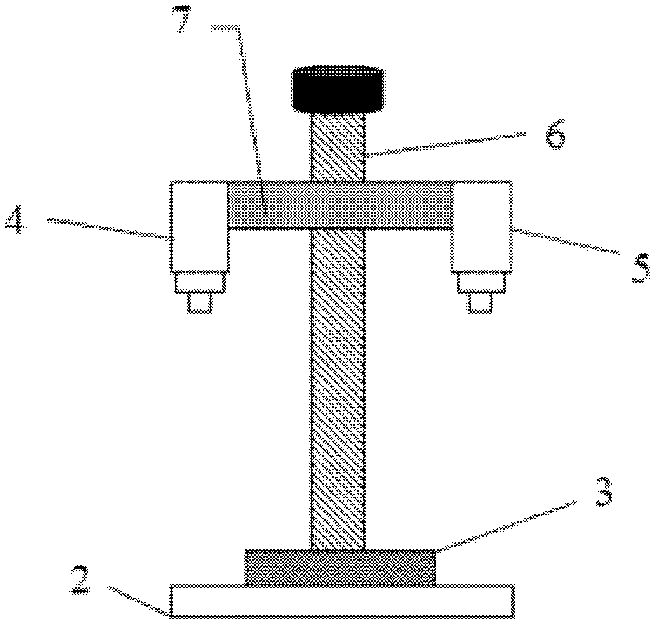
[0022] An infrared microscopic system, comprising a support, a stage 2, a target object 3, a visible microscopic camera 4 and an infrared microscopic camera 5, the target object is placed on the stage; the visible microscopic camera and the infrared microscopic camera are respectively placed on the support and above the stage, the optical axes of the visible microscopic camera and the infrared microscopic camera are parallel to each other and perpendicular to the upper side of the stage, the The visible microscopic camera and the infrared microscopic camera can move up and down and position relative to the stage along the support at the same time, and the visible microscopic camera and the infrared microscopic camera can respectively move left and right along the horizontal plane where they are located and make the Its lens is facing the target object on the stage.

[0023] Preferably, the above-mentioned visible microscopic camera and infrared microscopic camera can be moved ...


PUM


Abstract

The invention discloses an infrared microscope system and a method for achieving image fusion thereof. The method comprises the following steps: first, a visible image is rotated, then, corresponding rotation is conducted on an infrared image, afterwards, stretching transformation is conducted on the rotated infrared image, wherein in the process of the stretching transformation, a feature point on the visible image is used as a reference coordinate, the specific value of the coordinate of a reference point on the infrared image and the coordinate of the feature point corresponding to the coordinate of the reference point is used as a ratio to conduct stretching transformation respectively so as to obtain the transformed infrared image, then, the transformed infrared image and the visible image are overlapped, finally, the overlapped transformed infrared image and the visible image are rotated in the direction opposite to the direction of the infrared image so as to be restored to the original state of the infrared image, and so that an overlying fusion image of the infrared image and the visible image can be obtained. The infrared microscope system and the method for achieving the image fusion thereof can meet the demands of clear imaging and detail analyzing of micro devices and microstructures at the same time, and can also achieve imaging of infrared thermal distribution.

Description

technical field [0001] The invention relates to an infrared microscope system and a method for realizing image fusion thereof. Background technique [0002] Infrared imaging has a wide range of applications in microcosmic fields such as the design of semiconductor power devices, the reliability detection of integrated circuits, the actual effect analysis of laser diodes, the thermal distribution analysis of MEMS devices, the analysis of thermal properties of materials, and the temperature analysis of biological specimens. The microscope system came into being. However, since infrared thermal imaging cameras are usually only sensitive to a single wavelength or a specific band, such as 7-14 μm band, 3-5 μm band, etc., it is not sensitive to the brightness change of the scene, and the imaging resolution is low, and the details of the image are captured Far less abundant than visible light. The visible light imaging microscope is sensitive to the reflection of the target objec...

Claims


Application Information

Patent Timeline
Patent Type & Authority Applications(China)
IPC IPC(8): G01J5/00G06T5/50
Inventor 焦斌斌孔延梅程腾高杰李庆吴健雄
Owner INST OF MICROELECTRONICS CHINESE ACAD OF SCI
Why Eureka
Try Eureka