Method for imaging quality degradation amount of photoelectric platform in motion by using optical transfer function

An optical transfer function, optoelectronic platform technology, used in the testing of optical performance, television, electrical components, etc., can solve problems such as degradation of imaging quality of optical systems

Inactive Publication Date: 2013-07-24
CHANGCHUN INST OF OPTICS FINE MECHANICS & PHYSICS CHINESE ACAD OF SCI
View PDF7 Cites 9 Cited by
  • Summary
  • Abstract
  • Description
  • Claims
  • Application Information

AI Technical Summary

Problems solved by technology

[0006] In order to solve the problem of quantitatively measuring the degradation of the imaging quality of the optical system in a moving state, the present invention provides a random target method for measuring the optical modulation transfer function of an optoelectronic platform, by calculating the difference between the optical modulation transfer function of the optoelectronic platform in a static and moving state, In order to obtain the evaluation of the photoelectric platform motion imaging quality degradation, the method of measuring the photoelectric platform motion imaging quality degradation with the optical transfer function

Method used


Image

  • Method for imaging quality degradation amount of photoelectric platform in motion by using optical transfer function
  • Method for imaging quality degradation amount of photoelectric platform in motion by using optical transfer function
  • Method for imaging quality degradation amount of photoelectric platform in motion by using optical transfer function

Examples


Embodiment Construction

[0024] Invention idea of ​​the present invention is:

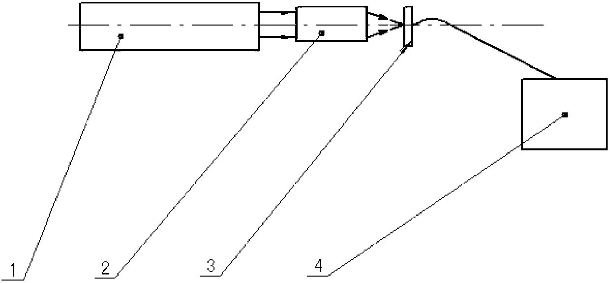
[0025] Fix the photoelectric platform on the swinging platform. When the swinging platform is stationary, the visual axis of the photoelectric platform is aligned with the random target pattern of white noise. The optical transfer function value of the photoelectric platform is measured by the random target method. Start the oscillating platform to make it move along the pitch and azimuth directions with a certain frequency and swing amplitude. The image quality of the optoelectronic platform will be reduced due to the influence of external swing, shaking and jitter.

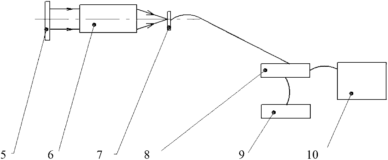
[0026] Start the servo stabilization system of the optoelectronic platform, the servo stabilization system will move in the opposite direction to the swinging platform, offset the impact of the swinging platform movement, stabilize the visual axis of the optoelectronic platform in the inertial space, the visual axis of the optoelectronic platform is still ali...


PUM


Abstract

The invention relates to a method for imaging quality degradation amount of a photoelectric platform in motion by using an optical transfer function. The method comprises the following steps of fixing the photoelectric platform on a swing table, aligning an optical axis of the photoelectric platform at a white noise random target pattern when the swing table is static, using a random target method to measure an optical transfer function value when the swing table is static, starting the swing table to enable the swing table to move along pitching and azimuth directions at certain frequency and certain swing amplitude, aligning the optical axis of the photoelectric platform at the white noise random target pattern, using the random target method to measure the optical transfer function value of the photoelectric platform subjected to servo control, comparing the optical transfer function value in a motion state and the optical transfer function value in a static state and obtaining the imaging quality degradation amount of the photoelectric platform in motion. The evaluation of imaging quality degradation of the photoelectric platform in motion is obtained by calculating the difference of the optical transfer function values in static and moving states by means of the method.

Description

technical field [0001] The invention relates to the technical field of testing the degradation of photoelectric platform motion imaging quality, in particular to a method for measuring the degradation of photoelectric platform motion imaging quality by using an optical transfer function. Background technique [0002] Under the conditions of airborne, vehicle-mounted, ship-borne, space-borne and other moving bases, the optoelectronic platform isolates most of the motion effects, but the residual jitter and vibration still damage the imaging quality of the optical system. As a result, blurring, defocusing, noise, deformation, and pixel aliasing of the optical system motion imaging will cause serious degradation. Accurately testing and evaluating the imaging quality in motion is the premise of improving the servo precision of the optoelectronic platform. There are many methods to evaluate the static imaging quality of an optical system, such as qualitative measurement methods ...

Claims


Application Information

Patent Timeline
Patent Type & Authority Applications(China)
IPC IPC(8): G01M11/02H04N17/00
Inventor 郎小龙嵇晓强陈晓露孙辉王平王子辰
Owner CHANGCHUN INST OF OPTICS FINE MECHANICS & PHYSICS CHINESE ACAD OF SCI
Why Eureka
Try Eureka