Measuring method for linear losses inside cavity of all-solid-state laser

A measurement method and laser technology, applied in the laser field, can solve problems such as limitations

Active Publication Date: 2016-09-28
北京泰和浩天科技有限公司
View PDF4 Cites 6 Cited by
  • Summary
  • Abstract
  • Description
  • Claims
  • Application Information

AI Technical Summary

Problems solved by technology

Although this method does not need to replace output coupling mirrors with different transmittances, it is also suitable for measuring the linear loss in the laser cavity after debugging and packaging. However, for high-gain single-frequency lasers, the serious thermal effect in the cavity will change the relaxation oscillation frequency, which limits the application of this method in the measurement of intracavity linear loss of all-solid-state high-gain single-frequency lasers

Method used


Image

  • Measuring method for linear losses inside cavity of all-solid-state laser
  • Measuring method for linear losses inside cavity of all-solid-state laser
  • Measuring method for linear losses inside cavity of all-solid-state laser

Examples


Embodiment approach 1

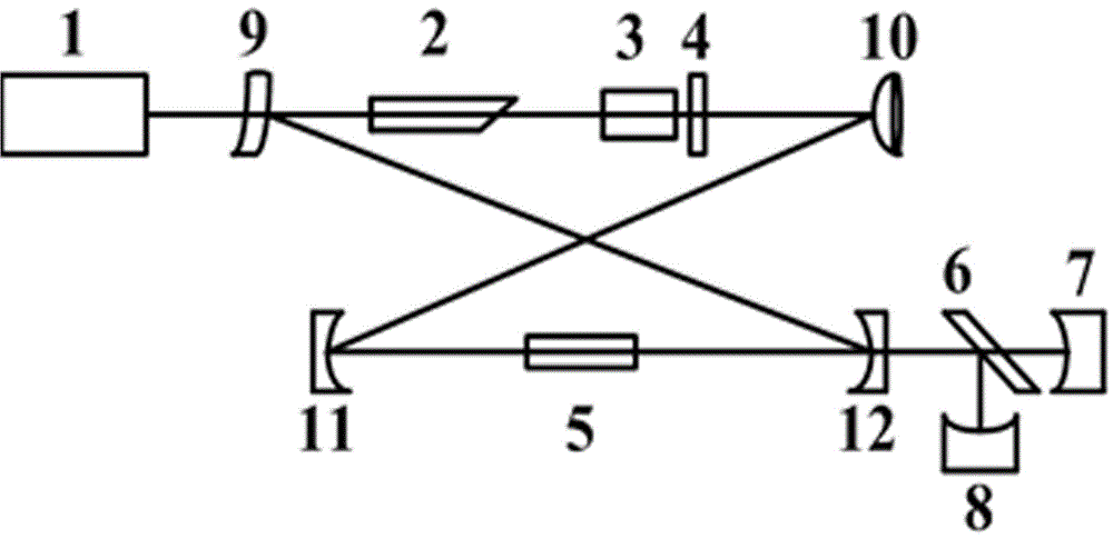
[0038] Implementation mode one: figure 1Shown is the measuring device of the present invention to the linear loss in the high-power four-mirror ring resonator, including pumping source 1, gain crystal 2, ring resonator made up of cavity mirrors (9, 10, 11, 12), set by A one-way device composed of a magneto-optical medium 3 and a half-wave plate 4 in a permanent magnet, a frequency doubling crystal 5, a beam splitter 6, a first power meter 7 and a second power meter 8. The pump light is focused to the center of the gain crystal 2 through the coupling system. The laser adopts a four-mirror ring resonant cavity structure, which is composed of cavity mirrors (9, 10, 11, 12). The cavity mirror 9 is a concave-convex mirror, the concave surface is coated with a high-transmittance film for pump light, and the convex surface is coated with a high-transmittance film for pump light and a high-reflection film for fundamental-frequency light; the cavity mirror 10 is a plano-convex mirror,...

Embodiment approach 2

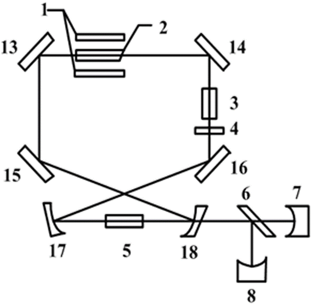
[0039] Implementation mode two: figure 2 Shown is the measurement device of the present invention to the linear loss in the six-mirror annular cavity of laser diode side pump, including pumping source 1, gain crystal 2, by cavity mirror (13, 14, 15, 16, 17, 18) A ring resonant cavity, a one-way device composed of a magneto-optical medium 3 and a half-wave plate 4 placed in a permanent magnet, a frequency doubling crystal 5, a beam splitter 6, a first power meter 7 and a second power meter 8. The light emitted by the pump source 1 is projected onto the gain crystal 2 after shaping and focusing, and the wavelength of the pump light is located at the absorption peak of the gain crystal 2 . The light-transmitting surface of the gain crystal 2 is cut into a certain wedge angle, which acts as a polarization beam splitter and facilitates maintaining the stability of the polarization state of the laser. The resonant cavity is composed of four plane mirrors (13, 14, 15, 16) and two p...

Embodiment approach 3

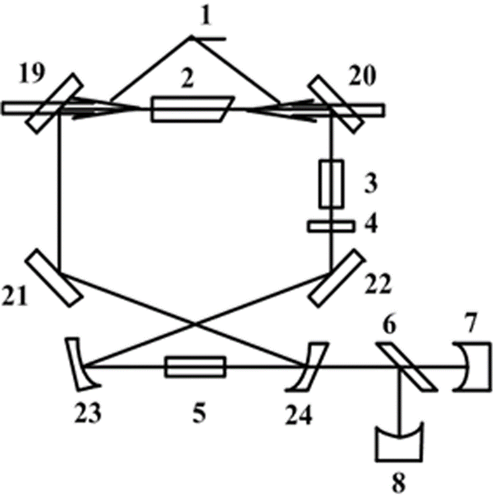
[0040] Implementation mode three: image 3 Shown is the measurement device of the linear loss in the cavity of the six-mirror annular cavity continuous single-frequency laser of the present invention that laser diode double-terminal pumping comprises pumping source 1, gain crystal 2, by cavity mirror (19,20,21,22 , 23, 24) composed of a ring resonant cavity, a one-way device composed of a magneto-optical medium 3 and a half-wave plate 4 placed in a permanent magnet, and a frequency doubling crystal 5. Compared with Embodiment 2, the main difference is that the pumping method is changed from side pumping to double-end pumping. The two end surfaces of the gain crystal 2 and the cavity mirrors 19 and 20 are coated with a high-transmittance film for pump light. The frequency doubling crystal 5 is located at the beam waist of the fundamental mode between the cavity mirror 23 and the cavity mirror 24 to ensure high nonlinear conversion efficiency. The frequency doubling crystal 5 ...


PUM


Abstract

The invention relates to a measuring method for linear losses inside a cavity of an all-solid-state laser. A pumping source (1), a gain crystal (2), ring resonant cavity, an isolator, a beam splitter (6), a first power meter (7),and a second power meter (8) are arranged, wherein the isolator is formed by a magneto-optical media (3) and a half-wave plate (4) that are arranged in a permanent magnet. The measuring method is characterized in that a frequency multiplication crystal (5) having a non-linear effect is introduced into the resonant cavity, wherein a phase matching way of the frequency multiplication crystal (5) is an I type or II type non-critical phase matching way; output values of corresponding fundamental waves and second harmonics of any two working temperature points of the frequency multiplication crystal (5) are measured in a single frequency area; and then the two groups of numerical values are substituted into a linear loss expression inside a cavity to carry out calculation, so that a linear loss value inside the cavity of the laser as well as a numerical value of a pumping factor is obtained. The linear loss expression includes a non-linear transformation factor of the frequency multiplication crystal (5), a fundamental wave output power, a second harmonic output power, and a pumping factor.

Description

technical field [0001] The invention relates to the field of laser technology, in particular to a method for measuring the linear loss in the cavity of an all-solid-state laser, and is especially suitable for measuring the linear loss in the cavity of a stable-running all-solid-state single-frequency laser. Background technique [0002] All-solid-state single-frequency lasers are widely used in quantum information, quantum communication, gravitational wave detection and other fields due to their compact structure, small size, good beam quality, high long-term power stability, and low noise. In the production, development and maintenance of all-solid-state lasers, intracavity linear loss is also an important indicator. In order to obtain an efficient and stable all-solid-state laser, the intracavity linear loss of the laser must be known, because the intracavity linear loss and net gain of the laser The relationship between is an important factor in determining the operating ...

Claims


Application Information

Patent Timeline
IPC IPC(8): G01M11/02
CPCG01M11/02
Inventor 卢华东郭永瑞苏静彭堃墀
Owner 北京泰和浩天科技有限公司
Why Eureka
Try Eureka