Signal dithering measuring method and device

A measurement method and technology of a measurement device, which are applied in the direction of error detection/prevention using a signal quality detector, and can solve the problems of transmission signal delay, unidentifiable signal, and delayed response of the signal.

Inactive Publication Date: 2006-09-27
NASOFORM INC
View PDF0 Cites 5 Cited by
  • Summary
  • Abstract
  • Description
  • Claims
  • Application Information

AI Technical Summary

Problems solved by technology

[0007] However, the measurement of jitter may cause an error phenomenon of measurement value amplification due to the inability to generate an ideal reference signal source, so that the amount of additional jitter added to the measurement value (refer to figure 2 ), and the statistical characteristics of the jitter signal are not easy to converge, and it is easy to cause measurement distortion
In terms of hardware implementation, there are quite a lot of restrictions on the design and manufacture of high-speed signals. For example, when a high-speed signal passes through an inverter chain, because the speed is too fast, the signal inverted by the inverter has no time to respond, resulting in transmission The signal is delayed and makes the signal unrecognizable
Therefore, how to accurately measure jitter in a relatively low-speed environment still needs a breakthrough

Method used


Image

  • Signal dithering measuring method and device
  • Signal dithering measuring method and device
  • Signal dithering measuring method and device

Examples


Embodiment Construction

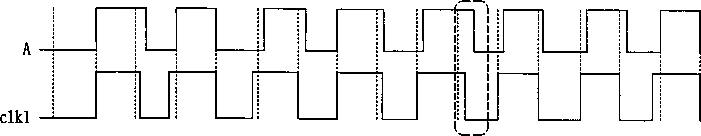
[0049] refer to figure 2 , the frequency of a high-speed data signal A is f, and a clock pulse signal clk1 with the same frequency as f is used to measure the jitter of the data signal A. If the clock pulse signal is to achieve high accuracy with an error of less than 2 picoseconds (ps) at high speed, it often must rely on special processes such as silicon germanium. If clk1 is produced by the current silicon manufacturing process, it is very likely to be jittered at high speed, which will be similar to the jitter of data signal A. figure 2 The phenomenon of jitter aliasing shown in the dotted box in , which greatly reduces the accuracy of jitter measurement.

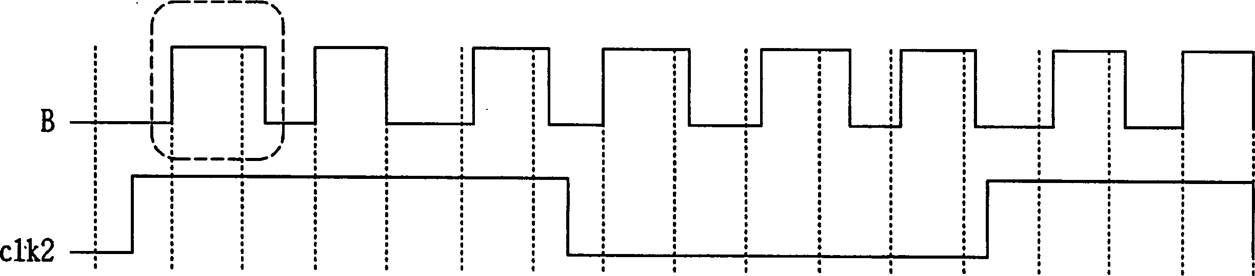
[0050] refer to image 3 , using a relatively low-speed clock pulse clk2 with a frequency of f / 3 to perform jitter measurement on the data signal B with a frequency of f. It is similar to a photography technique, by using the clk2 signal with a longer period to cover the entire pulse width of the data signal B, the p...


PUM


Abstract

The invention relates to a signal dither measuring method which comprises the following steps: first providing a first data signal and making the first data signal as a second data signal of another equivalent, wherein the frequency of the first data signal is multiply with the frequency of the second data signal and the up and down of the second data signal is as the same of the first data signal. Doing statistic to the high and low location width of the second data signal to generate a prediction shake flow, wherein it comprises the prediction shake value of the up and down of the second data signal. Then it computes an eye opening breadth by the shake distributing picture of the up and down rim.

Description

technical field [0001] The invention relates to a method and device for measuring signal jitter, in particular to a method and device for measuring jitter applied to high-speed signals. Background technique [0002] Jitter is defined as the deviation of the position of the signal edge from its ideal position in time, and is also often called timing distortion. It is caused by heat, electromagnetic noise, circuit instability or transmission loss. For data transmission systems, jitter will cause errors in data transmission, thereby reducing the overall reliability of the system. [0003] Jitter can be divided into quantitative jitter (deterministic jitter) and random jitter (random jitter). Random jitter belongs to Gaussian distribution in nature, and is generally caused by factors such as thermal noise and shot noise. Quantitative jitter includes the following components: periodic jitter (Periodic Jitter; PJ), data-dependent jitter (Data Dependent Jitter; DDJ), duty cycle ...

Claims


Application Information

Patent Timeline
Patent Type & Authority Applications(China)
IPC IPC(8): H04L1/20
Inventor 林俊伟陈获温陈弘斌
Owner NASOFORM INC
Why Eureka
Try Eureka