
microwave bandpass filter

A filter and microwave band technology, applied in waveguide devices, electrical components, circuits, etc., can solve the problems of high-performance broadband filters, complex filter structures, and poor performance, etc., and achieve simple structure, square coefficient Small and easy to process

Inactive Publication Date: 2015-10-28
NANJING UNIV
View PDF10 Cites 0 Cited by
  • Summary
  • Abstract
  • Description
  • Claims
  • Application Information

AI Technical Summary

Problems solved by technology

Broadband filters in the microwave segment can be realized by a variety of structures, such as microstrip lines, waveguides, etc., but the filters of these structures are often either complex in structure and expensive in cost or not good enough in performance, which cannot meet the requirements of high-performance broadband filters in practical applications. Require

Method used


Image

  • microwave bandpass filter
  • microwave bandpass filter
  • microwave bandpass filter

Examples


Embodiment Construction

[0021] Below in conjunction with accompanying drawing and specific embodiment, further illustrate the present invention, should be understood that these embodiments are only for illustrating the present invention and are not intended to limit the scope of the present invention, after having read the present invention, those skilled in the art will understand various aspects of the present invention Modifications in equivalent forms all fall within the scope defined by the appended claims of this application.

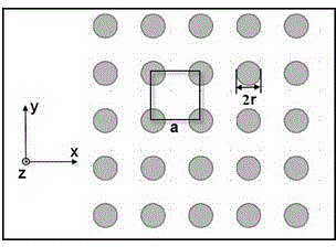
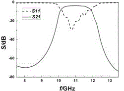
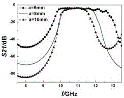
[0022] figure 1 It shows the microwave bandpass filter according to the present invention. In this embodiment, it mainly includes a magnetic photonic crystal and a foam material composed of 5*5 strontium-permanent ferrite cylinders (referred to as "magnetic cylinders") The base material, strontium-permanent ferrite cylinders are located in the through holes of the foam material. The magnetic photonic crystal is a tetragonal lattice, a is the lattice constant, and r is t...


PUM


Abstract

The invention discloses a microwave band-pass filter which comprises a substrate with through holes and a magnetic photonic crystal which is composed of a plurality of permanent magnetic ferrite columns. The permanent magnetic ferrite columns are arranged in the through holes. The microwave band-pass filter has the filter characteristics of being wide in frequency band, high in out-of-band rejection, and smooth in band, and meanwhile has the advantages of being small in size, simple in structure, easy to process, low in cost, easy to achieve, and the like.

Description

technical field [0001] The invention relates to a band-pass filter, in particular to a microwave band-pass filter, and more specifically to a magnetic photonic crystal band-pass filter. Background technique [0002] In high-performance communication systems, filters with low loss and high power capacity play an important role. In order to ensure the transmission of the signal waveform without distortion, a high-performance filter with small square factor and flat in-band is one of the essential devices. In recent years, as broadband communication technology has received more and more attention, the application of broadband filters has become more and more important. Broadband filters in the microwave segment can be realized by a variety of structures, such as microstrip lines, waveguides, etc., but the filters of these structures are often either complex in structure and expensive in cost or not good enough in performance, which cannot meet the requirements of high-performa...

Claims


Application Information

Patent Timeline
Patent Type & Authority Patents(China)
IPC IPC(8): H01P1/215
Inventor 伍瑞新顾艳
Owner NANJING UNIV
Learn More