Eureka AIR delivers breakthrough ideas for toughest innovation challenges, trusted by R&D personnel around the world.

Permanent-magnet synchronous motor start-up smooth switching method

A permanent magnet synchronous motor, smooth switching technology, applied in the direction of the starting device, etc., can solve the problems of speed jitter, position and current distortion, application range limitation, etc.

Active Publication Date: 2013-07-24
梵帝风机(泰州)有限公司
View PDF3 Cites 31 Cited by
  • Summary
  • Abstract
  • Description
  • Claims
  • Application Information

AI Technical Summary

Problems solved by technology

However, if the load changes, the position and current will be distorted when switching, and the speed will jitter, so the application range is greatly limited

Method used


Image

  • Permanent-magnet synchronous motor start-up smooth switching method
  • Permanent-magnet synchronous motor start-up smooth switching method
  • Permanent-magnet synchronous motor start-up smooth switching method

Examples


Embodiment 1

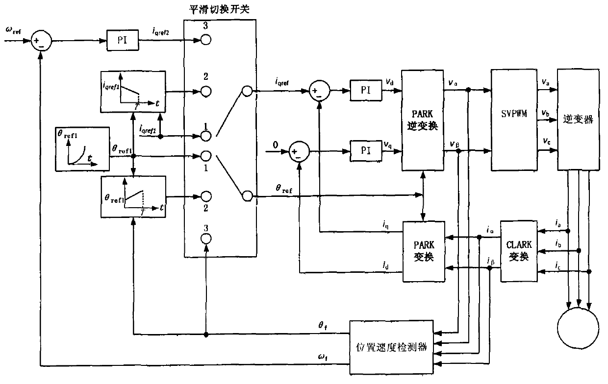
[0013] A permanent magnet synchronous motor starting smooth switching method in this embodiment, the permanent magnet synchronous motor rated power 120W, rated speed 1200rpm, speed range 400-1200rpm, including the following steps:

[0014] (1) Preset torque given current i qref1 Constantly equal to 0.9A, acceleration coefficient k=5000, switching transition time T=2s, so that the rotor has a given position angle θ ref1 Press ∫2πkt 2 dt changes, put the smooth switching switch to position 1, so that the torque current i of PARK transformation and inverse transformation qref equal to i qref1 , so that the PARK transformed and inverse transformed rotor position angle θ ref equal to theta ref1 , to force the permanent magnet synchronous motor to start and accelerate the rotation;

[0015] (2) When the position velocity estimator detects the permanent magnet synchronous motor velocity ω f When it reaches 360rpm, turn the smooth switch to position 2, so that the position angle...

Embodiment 2

[0018] A permanent magnet synchronous motor starting smooth switching method of the present embodiment, the permanent magnet synchronous motor rated power 60W, rated speed 900rpm, speed range 400-900rpm, including the following steps:

[0019] (1) Preset torque given current i qref1 Constantly equal to 0.5A, acceleration coefficient k=3000, switching transition time T=3s, so that the rotor has a given position angle θ ref1 Press ∫2πkt 2 dt changes, put the smooth switching switch to position 1, so that the torque current i of PARK transformation and inverse transformation qref equal to i qref1 , so that the PARK transformed and inverse transformed rotor position angle θ ref equal to theta ref1 , to force the permanent magnet synchronous motor to start and accelerate the rotation;

[0020] (2) When the position velocity estimator detects the permanent magnet synchronous motor velocity ω f When it reaches 300rpm, turn the smooth switch to position 2, so that the position a...


PUM


Abstract

The invention provides a permanent-magnet synchronous motor start-up smooth switching method. The method includes the following steps: presupposing that given torque current is identically 1.5 times that of rated current of a permanent magnet synchronous motor; presupposing that a rotor position angle is increased progressively at a T-squared growth rate, and enabling the permanent magnet synchronous motor to rotate at a constant accelerated speed; when the speed of the permanent magnet synchronous motor reaches 30% of a rated rotation speed, beginning to carry out switching transition, enabling a rotor position angle used for PARK transformation and reverse transformation to gradually approach an actual rotor position angle acquired by a position and speed estimator, and meanwhile, enabling the presupposed torque current to gradually approach torque current calculated by adopting the actual rotor position angle; and when time for switching transition arrives, switching closed-loop control states of the speed, the position and the current. The method can achieve the purposes that the rotor position and phase current are undistorted and the rotation speed does not oscillate in start-up switching of the permanent-magnet synchronous motor only by one-time parameter setting under any load.

Description

technical field [0001] The invention relates to a permanent magnet synchronous motor, in particular to a position sensorless magnetic field orientation control permanent magnet synchronous motor for loads such as fans, pumps and compressors. A method for smooth switching of current three closed loops. Background technique [0002] Field Oriented Control is currently recognized as the most advanced motor control theory in the industry, which enables permanent magnet synchronous motors to operate at any speed with higher efficiency, better dynamic response and smaller torque fluctuations. At present, the field-oriented control system of permanent magnet synchronous motors generally adopts the three closed-loop control methods of position, speed and current. In order to calculate the torque current component and flux current component required for the operation of permanent magnet synchronous motors, it is necessary to obtain reliable rotor information in real time. . For hig...

Claims


Application Information

Patent Timeline
IPC IPC(8): H02P6/20
Inventor 薛晓明陈震时倩
Owner 梵帝风机(泰州)有限公司
Why Eureka
Eureka Blog
Learn More