

Dimmer and switch suitable for driving a capacitive or complex capacitive-esistive load such as liquid crystal film
A capacitive load, dimmer technology, applied in nonlinear optics, instruments, optics, etc., can solve problems such as changing the light output intensity
Active Publication Date: 2013-07-24
GAUZY
View PDF3 Cites 1 Cited by
- Summary
- Abstract
- Description
- Claims
- Application Information
AI Technical Summary
Problems solved by technology
It is possible to change the intensity of the light output by increasing or decreasing the RMS voltage and thus increasing the average power of the lamp
Method used
View moreImage
Smart ImageViewing Examples

Examples
Embodiment approach 1
[0041] Embodiment 1: Transparency adjustment system, which includes:
[0042] a transparent physical element, which can have an infinite number of transparent states, whose electrical behavior is that of a capacitive load; and
[0043] A power dimmer device operative to provide AC current to the transparent physical element to produce a set of transparency states including a plurality of transparency states other than full transparency.
Embodiment approach 2
[0044] Embodiment 2: The system of Embodiment 1, wherein the transparent physical element comprises a liquid crystal (LC) film.
Embodiment approach 3
[0045] Embodiment 3: The system of Embodiment 1, wherein the set of transparency states further includes a state of full transparency.
Login to View More PUM
 Abstract
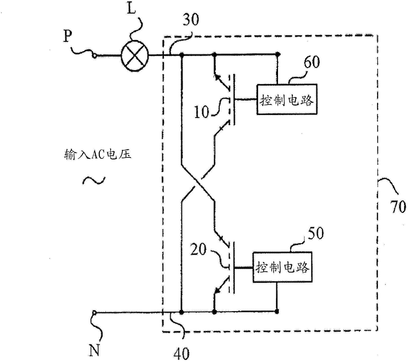
A transparency adjustment system comprising a transparent physical element whose electrical behavior is that of a capacitive load; and a power dimmer apparatus operative to provide AC current to the transparent physical element to generate a set of transparency states including a plurality of transparency states other than full transparency. Included in the scope of the invention is a system which changes the state of a load such as LC film from transparent to translucent in a single step rather than gradually.
Description
[0001] References to Co-Pending Applications [0002] Priority is claimed to U.S. Provisional Application No. 61 / 386,728, filed September 27, 2010, entitled "Dimmer and switch suitable for driving capacitive and complex capacitive-resistive load such as liquid crystal film." field of invention [0003] The present invention relates generally to transparent objects, and more particularly to affecting the transparency of an object. Background of the invention [0004] Conventional techniques pertaining to certain embodiments of the present invention are described, inter alia, in the following publications: [0005] Wikipedia states: "A dimmer is a device used to vary the brightness of a light. By increasing or decreasing the RMS voltage and thus increasing the average power of the lamp, it is possible to vary the intensity of the light output. While variable voltage devices are used for various purposes , the term "dimmer" is generally used for the purpose of dimmers used to ...
Claims
Login to View More Application Information
Patent Timeline
 IPC IPC(8): G02F1/133E06B9/24G02F1/1334
CPCG02F1/13306E06B2009/2464E06B9/24G02F1/1334G02F1/133362
Inventor迪米特里·多布仁克阿德里安·洛费尔伊亚尔·比索
OwnerGAUZY