Light-emitting device

A technology of light-emitting devices and light-emitting elements, which is applied in the direction of light-emitting materials, lighting devices, electroluminescent light sources, etc., can solve the problems of longer wavelengths and undisclosed issues, and achieve the effects of reduced luminous efficiency suppression and high color rendering

Active Publication Date: 2013-07-24
CITIZEN ELECTRONICS CO LTD
View PDF7 Cites 27 Cited by
  • Summary
  • Abstract
  • Description
  • Claims
  • Application Information

AI Technical Summary

Problems solved by technology

In the case of red, the visual perception efficiency decreases as the wavelength becomes longer
[0013] In addition, in the light-emitting device disclosed in Patent Document 2, although a number of embodiments are disclosed regarding a specific realization method of a red phosphor for re

Method used


Image

  • Light-emitting device
  • Light-emitting device
  • Light-emitting device

Examples


Embodiment 1

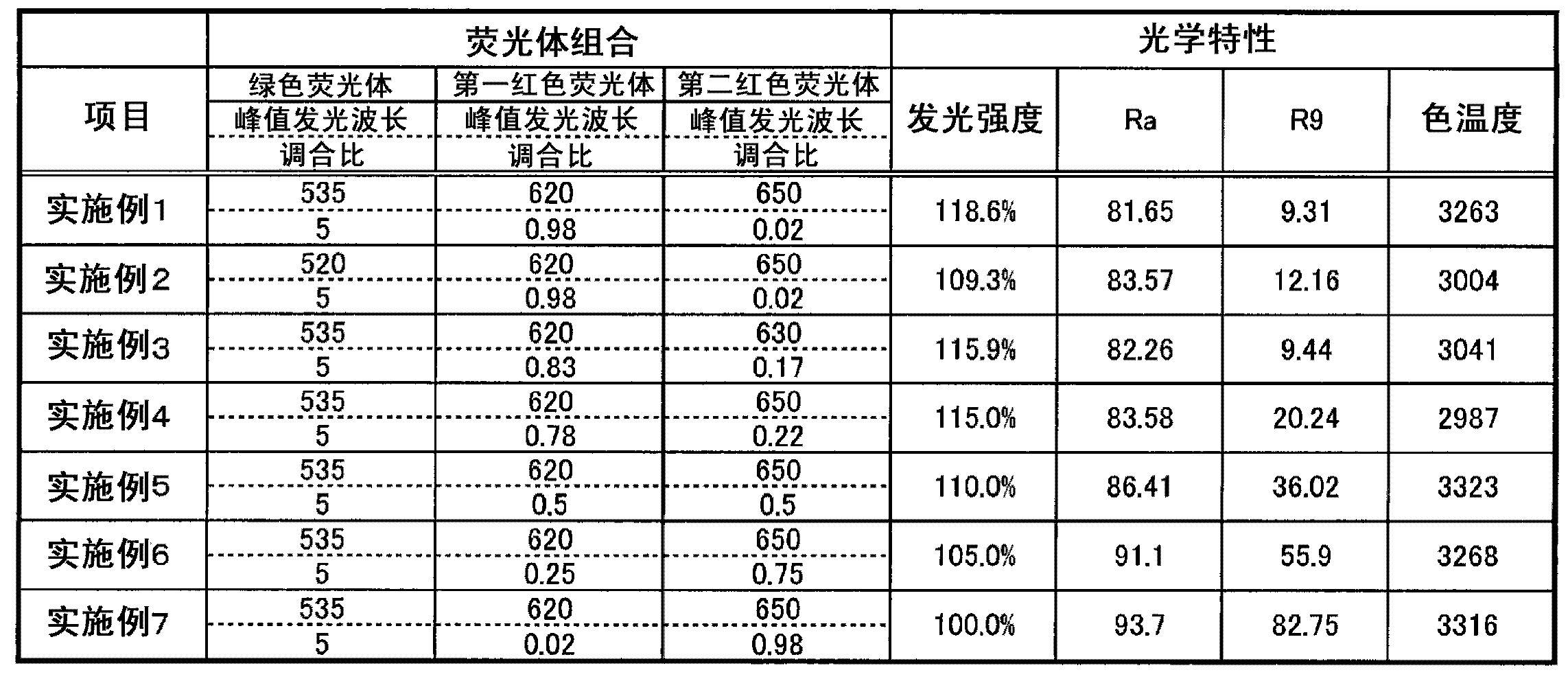
[0064] In Example 1, as the green phosphor, Al having a peak emission wavelength around 535 nm was used. 5 Lu x o y : Ce-based phosphor; (Sr, Ca)AlSiN having a peak emission wavelength around 620nm was used as the first red phosphor 3 : Eu-based phosphor; as the second red phosphor, CaAlSiN having a peak emission wavelength around 650nm is used 3 :Eu-based phosphor. In addition, the mixing ratio of the green phosphor, the first red phosphor, and the second red phosphor was 5:0.98:0.02. The relative value of luminous intensity (based on the lowest luminous intensity in Examples 1-7) is 118.6%, the average color rendering index Ra is 81.65, the special color rendering index R9 is 9.31, and the color temperature is 3263K.

Embodiment 2

[0066] In Example 2, as the green phosphor, Ca which has a peak emission wavelength around 520 nm is used. 3 (Sc, Mg) 2 Si 3 o 12 : Ce-based phosphor; (Sr, Ca)AlSiN having a peak emission wavelength around 620nm was used as the first red phosphor 3 : Eu-based phosphor; as the second red phosphor, CaAlSiN having a peak emission wavelength around 650nm is used 3 :Eu-based phosphor. In addition, the mixing ratio of the green phosphor, the first red phosphor, and the second red phosphor was 5:0.98:0.02. The difference from Example 1 is the peak emission wavelength of the green phosphor and the phosphor material.

[0067] The relative value of luminous intensity is 109.3%, the average color rendering index Ra is 83.57, the special color rendering index R9 is 12.16, and the color temperature is 3004K. Compared with Example 1, the peak emission wavelength of the green phosphor is shortened, so the emission intensity is slightly lowered, but the color rendering property is impro...

Embodiment 3

[0069] In Example 3, as the green phosphor, Al having a peak emission wavelength around 535 nm was used. 5 Lu x o y : Ce-based phosphor; (Sr, Ca)AlSiN having a peak emission wavelength around 620nm was used as the first red phosphor 3 : Eu-based phosphor; (Sr, Ca)AlSiN having a peak emission wavelength around 630nm is used as the second red phosphor 3 :Eu-based phosphor. In addition, the mixing ratio of the green phosphor, the first red phosphor, and the second red phosphor was 5:0.83:0.17. The difference from Example 1 is the peak emission wavelength of the second red phosphor, the phosphor material, and the blending ratio of the first and second red phosphors.

[0070] The relative value of luminous intensity is 115.9%, the average color rendering index Ra is 82.26, the special color rendering index R9 is 9.44, and the color temperature is 3041K. Compared with Example 1, the peak emission wavelength of the second red phosphor is shortened, but because the blending ratio...


PUM

PropertyMeasurementUnit
Particle sizeaaaaaaaaaa
Viscosityaaaaaaaaaa

Abstract

Disclosed is a high color rendering, high-efficiency light-emitting device capable of use in general lighting applications and which, in a state in which the average color rendering index (Ra) and the special color rendering index (R9) are maintained at high values, suppresses as much as possible reduction of the light-emission efficiency. The disclosed light-emitting device is provided with: at least one light-emitting element (6) which radiates light having a peak light-emission wavelength in the region from near-ultraviolet to blue; and a phosphor layer (5) containing green phosphors which are excited by the primary light emitted from the light-emitting element (6) and emit light having a peak emission wavelength in the green region, first red phosphors which are excited by the aforementioned primary light and emit light having a peak emission wavelength in the red region, and second red phosphors which, excited by the aforementioned primary light, emit light having a peak emission wavelength in the red region but different from that of the aforementioned first red phosphors.

Description

technical field [0001] The present invention relates to a light-emitting device that can be used as a light source of lighting fixtures and display devices, and more particularly, to a light-emitting device that can achieve high color rendering while maintaining or minimizing reduction in luminance. Background technique [0002] Various semiconductor light-emitting devices such as lighting devices using semiconductor light-emitting elements (hereinafter, appropriately referred to as "light-emitting elements") have been developed, and various means for improving output performance have been studied. In particular, in light-emitting devices that can be used for general lighting applications, it is important to have high color rendering (basically, the average color rendering index Ra is 80 or more, the US Energy Star standard, etc.) in terms of performance. [0003] As a representative method of realizing white light emission with a semiconductor light emitting device, the fol...

Claims


Application Information

Patent Timeline
IPC IPC(8): H01L33/50
CPCH01L33/507H01L25/0753H01L2224/48137H01L33/504H01L2224/48091H05B33/12C09K11/77348H01L2924/00014H01L33/486H01L33/505H01L33/62
Inventor 石崎真也
Owner CITIZEN ELECTRONICS CO LTD
Why Eureka
Try Eureka