Cleaning apparatus, equipment, and method
A technology for cleaning devices and cleaning liquids, which is applied to chemical instruments and methods, cleaning methods and utensils, cleaning methods using liquids, etc., and can solve the problems of complicated and expensive devices, inability to adjust ultrasonic exposure under cleaning conditions, etc.
- Summary
- Abstract
- Description
- Claims
- Application Information
AI Technical Summary
Problems solved by technology
Method used
Image

Examples
no. 1 example
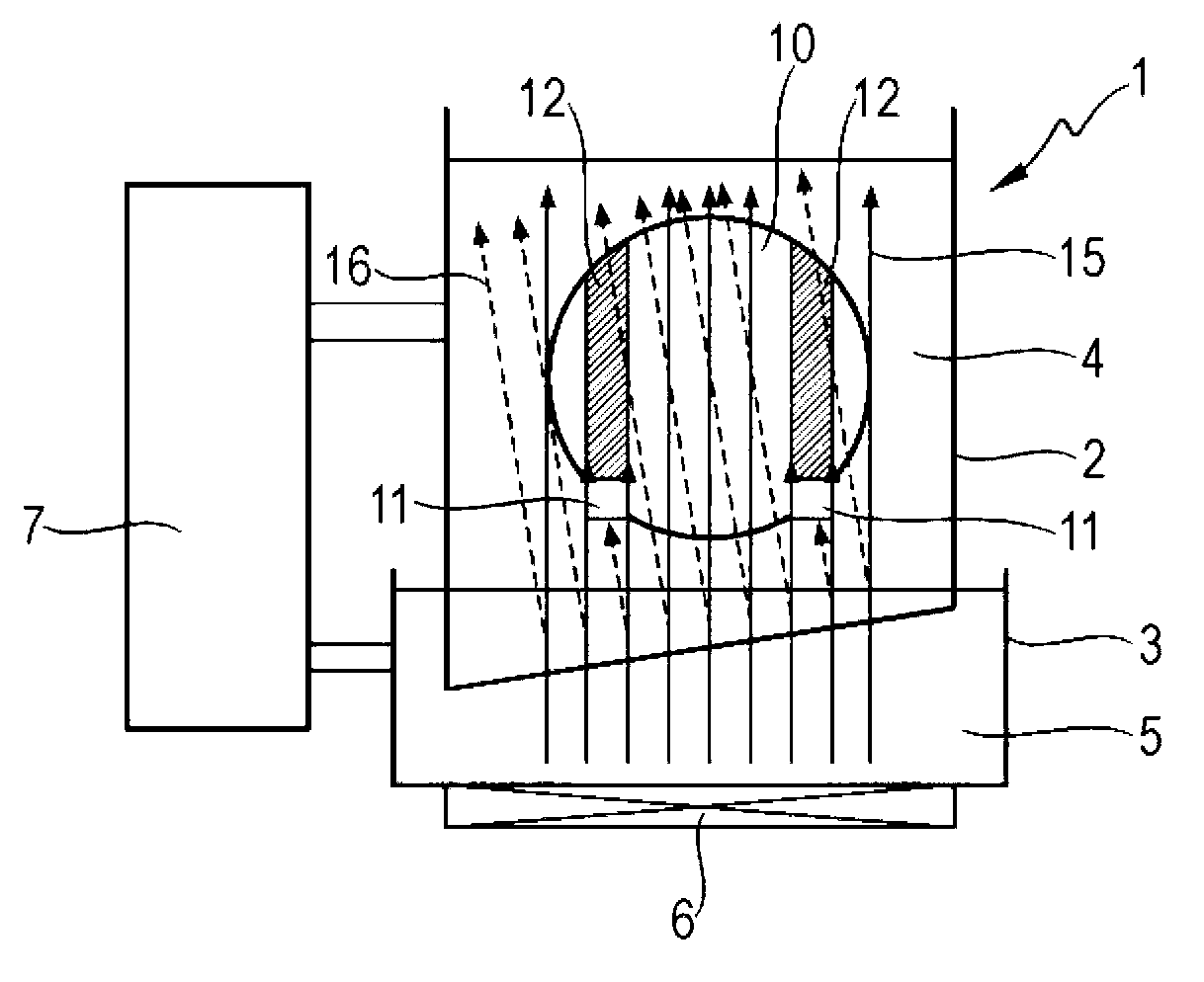
[0052] will refer to figure 1 The basic structure of the cleaning device of the present invention will be described. Such as figure 1 As shown, the present invention provides a cleaning device 1 , which includes a cleaning tank 2 , a coupling tank 3 , an ultrasonic generating unit 6 and a changing unit 7 . The cleaning tank 2 holds a cleaning solution 4 for cleaning a substrate 10 as an object to be cleaned. The coupling tank 3 holds the intermediate medium 5 , and the cleaning tank 2 has a portion (a part of the side wall and the bottom) in contact with the intermediate medium 5 . The bottom of the cleaning tank 2 is inclined relative to the bottom of the coupling tank 3 . The ultrasonic generating unit 6 is arranged at the coupling tank 3 , and ultrasonically oscillates the cleaning liquid 4 via the intermediate medium 5 . The ultrasonic generating unit 6 is connected and thereby fixed to the bottom wall of the coupling groove 3 . The changing unit 7 changes the differe...
no. 2 example
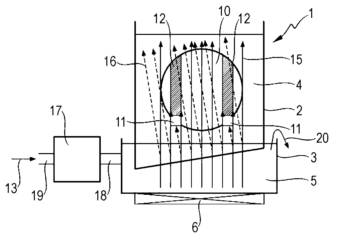
[0069] refer to Figure 8 , the present invention provides a second embodiment of the cleaning device 1, as will be described below. Figure 8 The cleaning device 1 basically has a figure 2 The configuration of the cleaning device 1, except that the former has a corresponding modification unit 7 (see figure 1 ) that are constructed differently. specifically, Figure 8 The cleaning device 1 is provided with two systems of pipes which respectively supply the intermediate medium to the coupling tank 3 . In one system, the pipe 18 connected to the coupling tank 3 is connected to an automatic valve 27 which is connected via pipe 19 to a water supply (eg a sink). The automatic valve 27 is supplied with water through the pipe 19 as indicated by the arrow 32 . Furthermore, in another system, the pipe 18 connected to the coupling tank 3 has the automatic valve 28 connected thereto. In addition, an automatic valve 28 is connected to an ethanol supply source (eg, an ethanol tank) ...
no. 3 example
[0078] refer to Figure 10 , the third embodiment of the present invention provides a cleaning apparatus 100 as will be described below. Such as Figure 10 As shown, cleaning apparatus 100 includes three cleaning units 41-43 and a substrate transfer element (not shown). The cleaning unit 42 and the cleaning unit 43 are basically similar in construction to figure 1 The cleaning device 1 and includes a modification unit 7 connected to the coupling tank 3 . Change Unit 7 can have the figure 2 , Figure 7 and Figure 8 The configuration of the modified units of the shown cleaning device 1 corresponds. The cleaning unit 41 also has a substantially similar figure 1 The configuration of the cleaning device 1, except the former does not include the modification unit 7. Accordingly, in the cleaning unit 41 , ultrasonic waves travel through the cleaning tank 2 in a fixed direction as indicated by the arrow 15 .
[0079] In contrast, cleaning unit 42 and cleaning unit 43 are pr...
PUM
 Abstract
Description
Claims
Application Information
 - R&D Engineer
- R&D Manager
- IP Professional
- Industry Leading Data Capabilities
- Powerful AI technology
- Patent DNA Extraction
Browse by: Latest US Patents, China's latest patents, Technical Efficacy Thesaurus, Application Domain, Technology Topic.
© 2024 PatSnap. All rights reserved.Legal|Privacy policy|Modern Slavery Act Transparency Statement|Sitemap