Method for positioning micro seismic source or acoustic emission source

A technology of acoustic emission sources and positioning methods, applied in positioning, measuring devices, instruments, etc., can solve problems such as the inability to eliminate the influence of sound velocity deviation, and achieve the effect of avoiding errors

Active Publication Date: 2011-07-20
CENT SOUTH UNIV
View PDF4 Cites 70 Cited by
  • Summary
  • Abstract
  • Description
  • Claims
  • Application Information

AI Technical Summary

Problems solved by technology

[0004] In short, the influence of sound velocity deviation on positioning

Method used


Image

  • Method for positioning micro seismic source or acoustic emission source
  • Method for positioning micro seismic source or acoustic emission source
  • Method for positioning micro seismic source or acoustic emission source

Examples


Embodiment 1

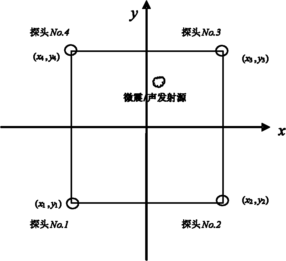
[0032] Such as figure 1 As shown, explain:

[0033] The position of the preset microseismic source / acoustic emission source is (0mm, 0mm), and the coordinates of the three sensors (x 1 ,y 1 ), (x 2 ,y 2 ), (x 3 ,y 3 ), (x 4 ,y 4 ) are (0mm, -10000mm), (8000mm, 0mm), (0mm, 6000mm), (-13000mm, 0mm); the moment when the microseismic source / acoustic emission source is transmitted to the four sensors to trigger the sensor recording is 2020μs, respectively, 2016μs, 2012μs, 2026μs. Take this example to explain the two-dimensional positioning problem in detail. In the actual positioning, the known quantities are the coordinates of the four sensors and the moment when the sensor triggers the recording. The position of the microseismic source / acoustic emission source is unknown. The reason given here is the purpose It is verified by the method proposed in this patent. The specific implementation steps are as follows:

[0034] (1) List the coordinate values ​​of the four senso...

Embodiment 2

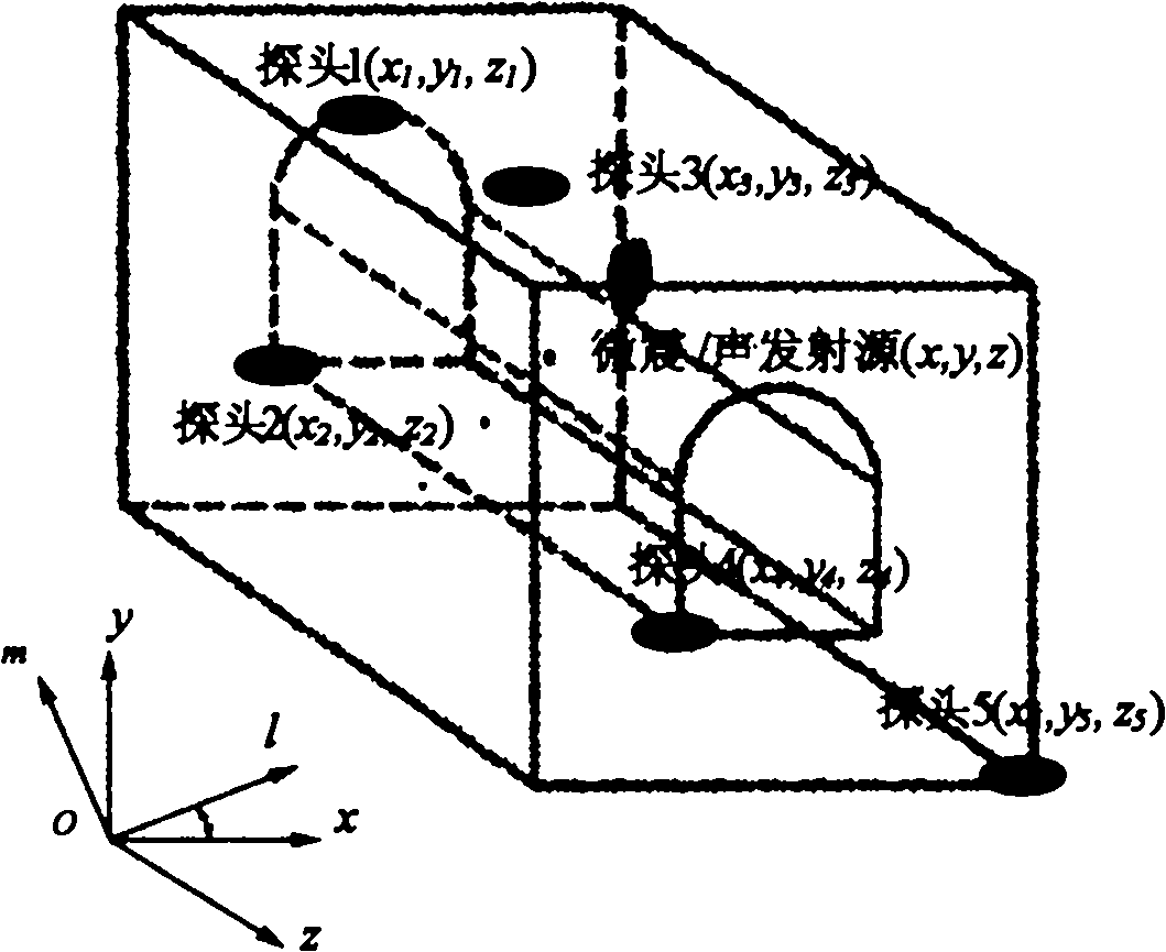
[0039] Such as figure 2 As shown, the preset position of a microseismic source / acoustic emission source is (0mm, 0mm, 0mm), and the coordinates of the five sensors (x 1,y 1 ,z 1 ), (x 2 ,y 2 ,z 2 , t 2 ), (x 3 ,y 3 ,z 3 ), (x 4 ,y 4 ,z 4 ) and (x 5 ,y 5 ,z 5 ) are (-80000, 0, 0), (0, 15000, 0), (60000, 0, 0), (0, 45000, 0), (0, 0, 55000), respectively. The five sensors correspond to the triggering time t 1 , t 2 , t 3 , t 4 , t 5 They are 5016μs, 5003μs, 5012μs, 5009μs, 5011μs respectively. Take this example to explain the three-dimensional positioning problem in detail. In the actual positioning, the known quantities are the coordinates of the five sensors and the moment when the sensor triggers the recording. The position of the microseismic source / acoustic emission source is unknown. The reason why it is given here is to Verify by the method proposed in this patent. The specific implementation steps are as follows:

[0040] (1) Arrange five sensors (...


PUM


Abstract

The invention discloses a method for positioning a micro seismic source or an acoustic emission source, which comprises the following steps of: placing a plurality of acoustic emission transducers nearby an object to be detected, and solving position coordinates of the micro seismic source or the acoustic emission source by using a nonlinear least square regression method, such as a simplex acceleration method or a Marquardt method or the like, according to the coordinate values and the time difference of the positions of the known transducers and according to a distance operational formula. The acoustic emission positioning method disclosed by the invention does not need to measure or preset acoustic velocity, can avoid the influence of acoustic velocity measurement on positioning, improves the positioning precision, and is convenient and practical in practical engineering application compared with a traditional method.

Description

technical field [0001] The invention relates to a positioning method for a microseismic source or an acoustic emission source. technical background [0002] How to accurately locate the source of material damage or the accompanying microseismic / acoustic emission in the early stage of rockburst is very important. The source localization technology of microseismic / acoustic emission is one of the core issues in the research of acoustic emission technology, and its positioning accuracy reflects the degree of conformity between the detected position of the sound source and the real position. [0003] Many scientific workers have done a lot of research on the source location of acoustic emission, and proposed many source location methods for acoustic emission, such as the location method based on modal analysis and wavelet transform, and the location method based on neuron network system, etc., but At present, the positioning of acoustic emission instruments still generally adopt...

Claims


Application Information

Patent Timeline
IPC IPC(8): G01S5/22
Inventor 李夕兵董陇军宫凤强周子龙
Owner CENT SOUTH UNIV
Why Eureka
Try Eureka