Paper shredding device for hydrapulper

A hydraulic pulper and paper shredding technology, applied in the direction of raw material separation, etc., can solve problems such as low percussion degree, pulper jamming, motor burnout, etc., to improve flatness and smoothness, speed up pulping speed, improve percussion effect

Inactive Publication Date: 2013-07-31
杭州富阳以勒科技有限公司
View PDF11 Cites 5 Cited by
  • Summary
  • Abstract
  • Description
  • Claims
  • Application Information

AI Technical Summary

Problems solved by technology

[0002] Since the inside and outside of the shredder knife in the current pulper are linear, it is easy to wrap the packing belt, woven bag, and iron wire on the blade, causing the pulper to be stuck, and even burn the motor in severe cases. , the existing pulper has problems such as large power consumption, low work efficiency, and low percussion degree

Method used


Image

  • Paper shredding device for hydrapulper
  • Paper shredding device for hydrapulper

Examples


Embodiment 1

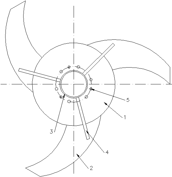
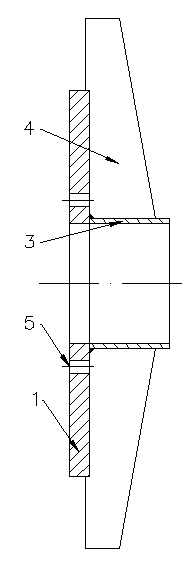
[0015] Such as Figure 1 ~ Figure 2 As shown, the shredding device used in the hydraulic pulper provided by this embodiment includes a cutter head 1, and the outer ring of the cutter head 1 is fixedly connected with three shredding knives 2 uniformly distributed in the circumferential direction. The inner side and the outer side of the knife 2 are arc lines, and a cover 3 is fixedly connected to the cutterhead 1, the central axis of the cover 3 is collinear with the central axis of the cutterhead 1, and the outer ring of the cover 3 There are three baffles 4 evenly distributed in the circumferential direction fixedly connected, a part of the bottom surface of the baffle 4 close to the cover 3 is fixedly connected with the cutterhead 1, and the rest is fixedly connected with the shredder knife 2, and the baffles 4 and the height of the fixed end of the sleeve cover 3 are twice the height of the other end of the baffle, and the cutter head 1 is provided with a threaded hole 5 fo...

Embodiment 2

[0018] In the present embodiment, the structure is the same as that in Example 1, and the pulper with a volume of 35 m3 is selected, wherein the diameter of the cutter head is 995 mm, the thickness of the cutter head is 55 mm, and the thickness of the shredder is 50 mm. The distance from the central axis to the outermost end of the baffle is 640mm, and the distance from the inner side of the shredder away from the cutter head to the outer ring of the cutter head is 635mm, which also increases the line speed by 5-6m per second, and can generate a strong force during operation. The vortex drags the material towards the shredder, where it is quickly crushed by the shredder.


PUM

PropertyMeasurementUnit
diameteraaaaaaaaaa
thicknessaaaaaaaaaa
diameteraaaaaaaaaa

Abstract

The invention discloses a paper shredding device for a hydrapulper. The device comprises a cutter disc, wherein the external ring of the cutter disc is fixedly connected with three paper shredding cutters which are uniformly distributed along the circumferential direction; the inner and outer sides of the paper shredding cutters are arc; a sleeve cover is fixedly connected on the cutter disc; the central axes of the sleeve cover and the cutter disc are superposed; the external ring of the cutter disc is fixedly connected with three baffles which are uniformly distributed along the circumferential direction; parts, which are close to the sleeve cover, of the bottom end faces of the baffles are fixedly connected with the cutter disc, and the rest parts of the bottom end faces of the baffles are fixedly connected with the paper shredding cutters; and the heights of the ends, which are fixed with the sleeve cover, of the baffles are more than the heights of the other ends of the baffles. The paper shredding device for the hydrapulper has the advantages that under the condition of not changing the original power, the linear velocity is accelerated by 5-6m/second, and raw materials can be dragged towards the paper shredding cutters under a powerful vortex generated in the operation process and quickly shredded by the paper shredding cutters, so that the pulping velocity is accelerated, and the beating degree is improved.

Description

technical field [0001] The invention relates to a paper shredding device, in particular to a paper shredding device used in a hydraulic pulper. Background technique [0002] Since the inside and outside of the shredder knife in the current pulper are linear, it is easy to wrap the packing belt, woven bag, and iron wire on the blade, causing the pulper to be stuck, and even burn the motor in severe cases. , the existing pulper has problems such as large power consumption, low work efficiency, and low degree of beating. Contents of the invention [0003] The technical problem to be solved by the present invention is to provide a paper shredding device used in a hydraulic pulper, which can greatly increase the linear speed and the beating degree without changing the driving force. [0004] In order to solve the above-mentioned technical problems, the paper shredding device used in the hydraulic pulper provided by the present invention includes a cutter head, and the outer ri...

Claims


Application Information

Patent Timeline
Patent Type & Authority Applications(China)
IPC IPC(8): D21B1/34
Inventor 骆旭东
Owner 杭州富阳以勒科技有限公司
Why Eureka
Try Eureka