
Centrifugal fan and clothes dryer with same

A technology for centrifugal fans and clothes dryers, applied in mechanical equipment, machines/engines, liquid fuel engines, etc., can solve problems such as poor airflow, reduced fan performance, and large motor cover, achieving high work efficiency and reducing Inlet turbulence and good airflow pattern

Inactive Publication Date: 2013-07-31
WUXI LITTLE SWAN CO LTD
View PDF10 Cites 15 Cited by
  • Summary
  • Abstract
  • Description
  • Claims
  • Application Information

AI Technical Summary

Problems solved by technology

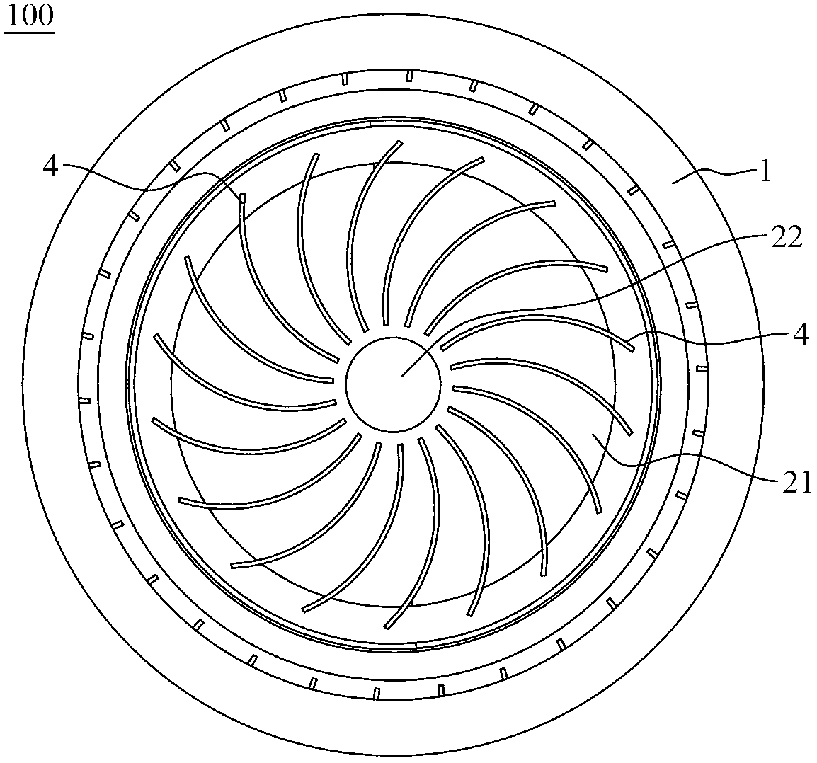
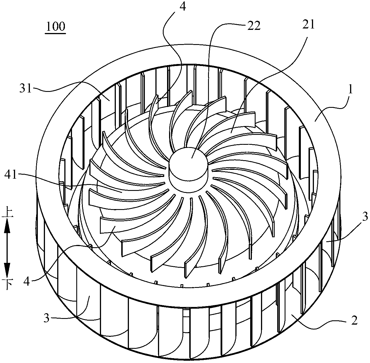
[0003] The centrifugal fan in the prior art usually has a motor cover in its central area, and the motor cover is large in size, which becomes the main obstacle for the airflow to flow into the central negative pressure area of ​​the centrifugal fan, and the airflow hits the surface of the motor cover during the flow to form a backflow As a result, the airflow at the air inlet of the centrifugal fan is not good, and the performance of the fan is reduced

Method used


Image

  • Centrifugal fan and clothes dryer with same
  • Centrifugal fan and clothes dryer with same
  • Centrifugal fan and clothes dryer with same

Examples


Embodiment Construction

[0038] Embodiments of the present invention are described in detail below, examples of which are shown in the drawings, wherein the same or similar reference numerals designate the same or similar elements or elements having the same or similar functions throughout. The embodiments described below by referring to the figures are exemplary only for explaining the present invention and should not be construed as limiting the present invention.

[0039] In describing the present invention, it should be understood that the terms "center", "longitudinal", "transverse", "upper", "lower", "front", "rear", "left", "right", " The orientations or positional relationships indicated by "vertical", "horizontal", "top", "bottom", "inner" and "outer" are based on the orientations or positional relationships shown in the drawings, and are only for the convenience of describing the present invention and Simplified descriptions, rather than indicating or implying that the device or element refe...


PUM


Abstract

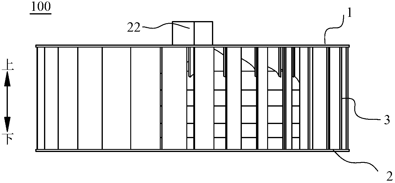
The invention discloses a centrifugal fan and a clothes dryer with the same. The centrifugal fan comprises a plurality of main blades arranged on the periphery of the centrifugal fan, and is characterized in that a plurality of radially distributed auxiliary blades are arranged on a mask, facing an air inlet direction, of the centrifugal fan. The centrifugal fan further comprises a wheel rim and a wheel disk, wherein the central area of the wheel disk forms a motor cover; the plurality of main blades are circumferentially arranged between the wheel rim and the wheel disk at intervals, and every two adjacent main blades define a first airflow passageway; the plurality of auxiliary blades surround a connection shaft sleeve and are arranged on the motor cover, and every two adjacent auxiliary blades define a second airflow passageway; and the first airflow passageways, the second airflow passageways and air inlets are communicated mutually. The centrifugal fan can effectively reduce inhibition of the motor cover, enable airflow at the air inlets of the centrifugal fan to flow better, and realize two-stage boosting and speed-increasing of the auxiliary blades and the main blades, so that the pressure of airflow at outlets of the centrifugal fan is obviously increased, and the efficiency of the fan is improved.

Description

technical field [0001] The invention relates to the field of household electrical appliances, in particular to a centrifugal fan and a clothes dryer with the same. Background technique [0002] Fans are roughly divided into axial fans and centrifugal fans according to the direction of gas flow. The centrifugal fan uses a high-speed rotating centrifugal fan to make the gas enter the centrifugal fan from the axial direction, and under the action of its centrifugal force, it is discharged from between the blades of the centrifugal fan in the radial direction. The centrifugal fan of the centrifugal fan is usually powered by a motor, and the rotation of the output shaft of the motor drives it to rotate at a high speed. [0003] The centrifugal fan in the prior art usually has a motor cover in its central area, and the motor cover is large in size, which becomes the main obstacle for the airflow to flow into the central negative pressure area of ​​the centrifugal fan, and the air...

Claims


Application Information

Patent Timeline
Patent Type & Authority Applications(China)
IPC IPC(8): F04D29/28
Inventor 陆彭飞黄华周福昌
Owner WUXI LITTLE SWAN CO LTD
Learn More