
Optical fiber reflector and method of utilizing optical fiber reflector to achieve PON monitoring

A reflector and optical fiber technology, applied in the field of optical communication, can solve the problems of high price and limited number of monitoring channels

Inactive Publication Date: 2013-07-31
GUILIN G LINK TECH
View PDF6 Cites 15 Cited by
  • Summary
  • Abstract
  • Description
  • Claims
  • Application Information

AI Technical Summary

Problems solved by technology

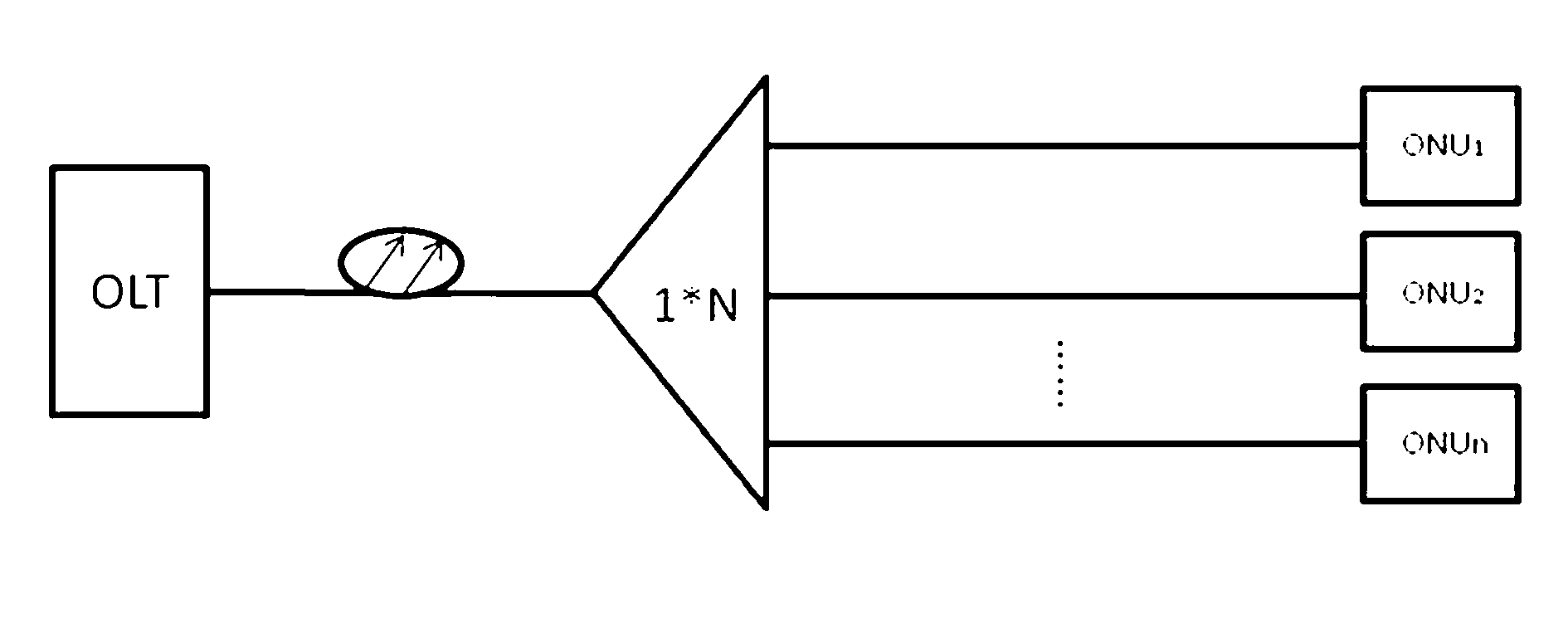
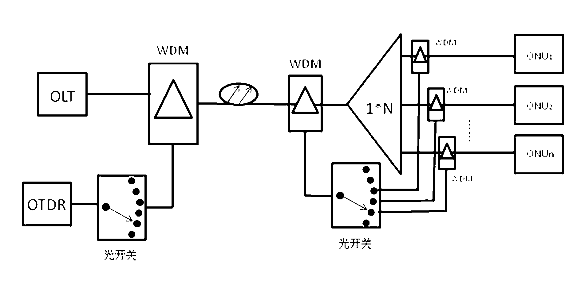
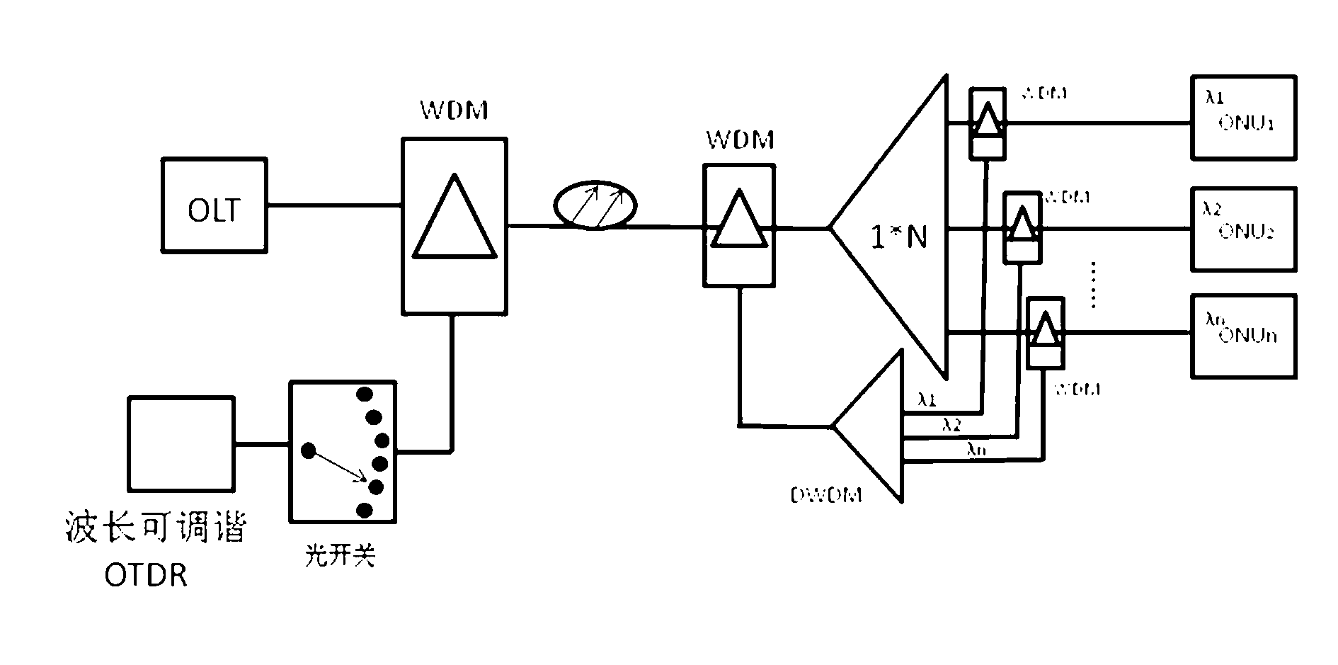
[0008] The DWDM frequency domain monitoring method requires the use of wavelength tunable OTDR, which is expensive and uses different wavelengths to monitor different channels. The wavelength resource limits the number of monitoring channels.

Method used


Image

  • Optical fiber reflector and method of utilizing optical fiber reflector to achieve PON monitoring
  • Optical fiber reflector and method of utilizing optical fiber reflector to achieve PON monitoring
  • Optical fiber reflector and method of utilizing optical fiber reflector to achieve PON monitoring

Examples


Embodiment Construction

[0028] The present invention will be further described below in conjunction with the accompanying drawings and embodiments.

[0029] An optical fiber reflector, comprising an optical input interface 1, an optical splitter 2, a built-in extension optical fiber 3, a reflection port 4, an optical output interface 5, and a packaging device 6; one end of the optical input interface 1 and the built-in extension optical fiber 3 is connected to the optical splitter 2 The input end of the optical splitter, the optical output interface 5 is connected to the branch port with a large branch ratio of the optical splitter 2, and the reflective port 4 is connected to the branch port with a small branch ratio of the optical splitter 2. The optical splitter 2, the built-in extension fiber 3 and the reflective port 4 are all encapsulated In the packaging device 6.

[0030] Both the optical input interface 1 and the optical output interface 5 use APC interfaces.

[0031] The branching r...


PUM


Abstract

The invention discloses an optical fiber reflector and a method of utilizing the optical fiber reflector to achieve PON (passive optical network) monitoring. The optical fiber reflector comprises an optical input interface (1), an optical branch device (2), a built-in extending optical fiber (3), a reflection port (4), an optical output interface (5) and a packaging implement (6), wherein the optical input interface and one end of the built-in extending optical fiber are connected with an input end of the optical branch device; the optical output interface is connected with a large-branch-ratio branch port of the optical branch device; the reflection port is connected with a small-branch-ratio branch port of the optical branch device; and the optical branch device, the built-in extending optical fiber and the reflection port are packaged in the packaging implement. According to a PON monitoring system achieved by utilizing the optical fiber reflector, a structure of a testing network can be simplified; the monitoring cost of the system can be lowered; and the low-cost PON network monitoring can be achieved.

Description

technical field [0001] The invention relates to the field of optical communication, in particular to an optical fiber reflector and a method for realizing PON network monitoring by using the device. Background technique [0002] With the acceleration of the process of optical fiber in and copper out, PON-based FTTB and FTTH passive optical networks are widely used, and the operation quality of optical cable networks is a problem that operators are very concerned about. NTT Japan’s PON network fault statistical distribution survey shows that user-side and ODN-side faults account for more than 90% of all PON network faults. How to accurately determine the fault responsibility (user side, ODN side, and central office side) as soon as possible to confirm the troubleshooting subject, Reduce invalid dispatch orders; how to reduce the amount of personnel and instrument configuration, and save investment is the focus of operators' operation and maintenance. Need to adopt effective ...

Claims


Application Information

Patent Timeline
IPC IPC(8): H04B10/071
Inventor 秦志斌肖丹谊周晓伟
Owner GUILIN G LINK TECH
Learn More