Pinch valve working state detecting device and detecting method

A technology of working state and detection device, which is applied in the direction of valve device, measuring device, measuring fluid pressure, etc., can solve the problem that the working and fault state of the pinch valve cannot be monitored, and achieve the effect of all-round monitoring

Pending Publication Date: 2020-08-25
苏州思迪机电有限公司
View PDF0 Cites 4 Cited by
  • Summary
  • Abstract
  • Description
  • Claims
  • Application Information

AI Technical Summary

Problems solved by technology

[0005] In order to solve the deficiencies in the prior art, the present invention provides a detection device and detection method for the working state of the pinch valve, which solves the problem that the working and fault states of the pinch valve cannot be monitored in the prior art

Method used


Image

  • Pinch valve working state detecting device and detecting method
  • Pinch valve working state detecting device and detecting method
  • Pinch valve working state detecting device and detecting method

Examples


Embodiment 1

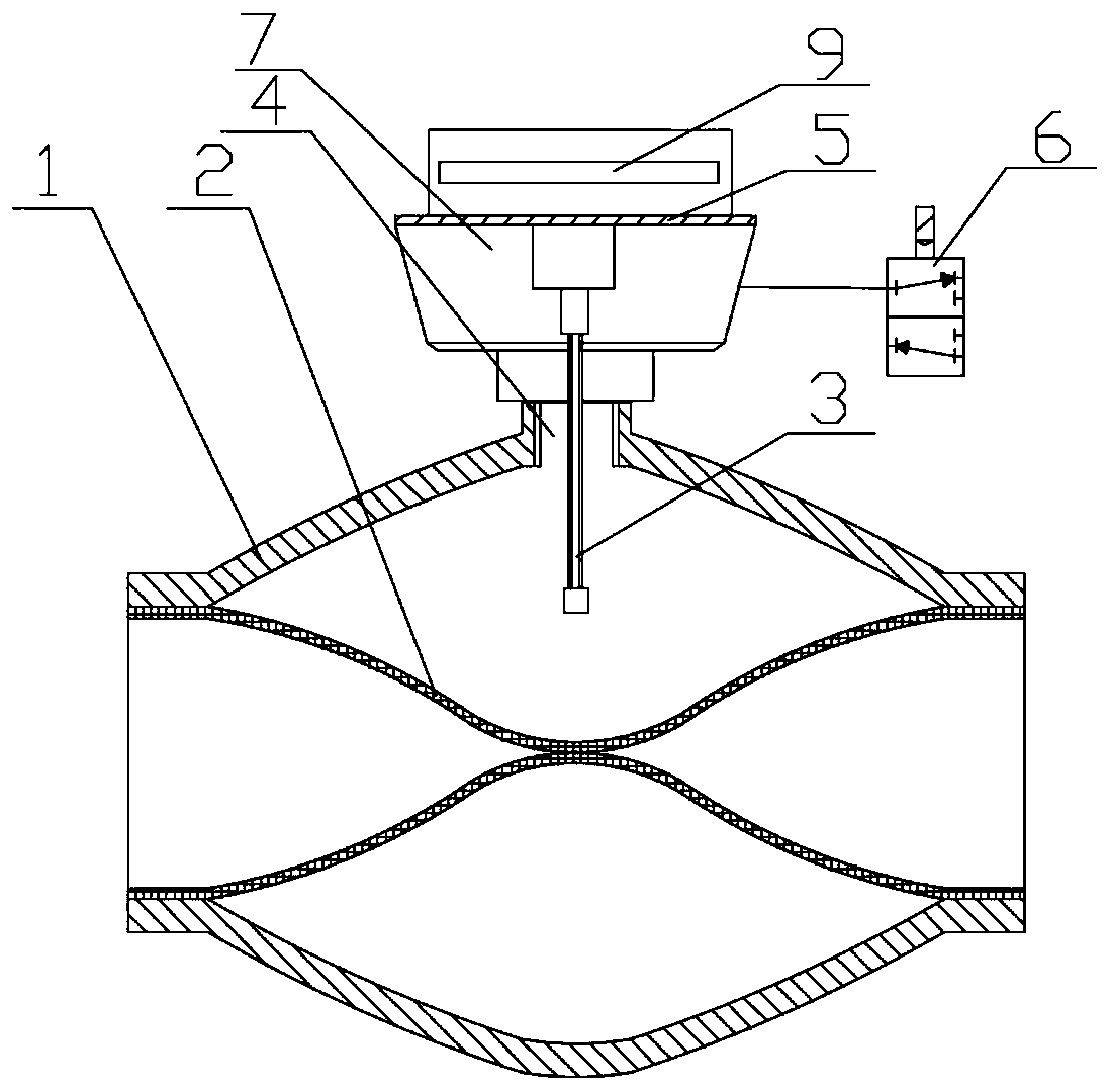
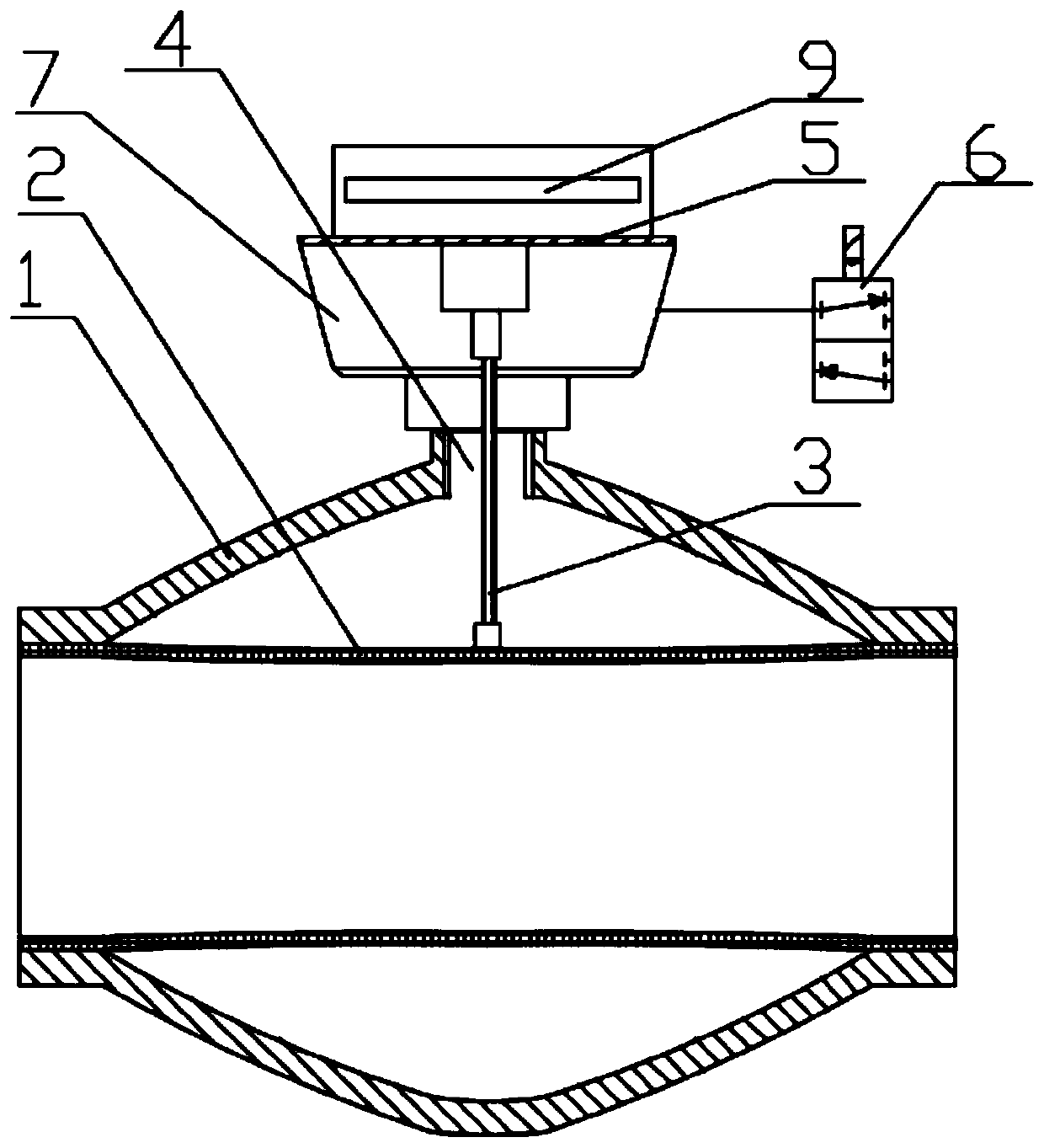
[0036] This embodiment discloses a method for detecting the working state of a pinch valve. In this embodiment, the position of the rubber tube sleeve 2 in the valve is detected through the capacitance probe 3. The specific control strategy is shown in the following table:

[0037]

[0038] The control system detects the solenoid valve power supply voltage, the pressure sensor signal and the radial position signal of the hose sleeve in the valve in real time.

[0039] 1. When both the solenoid valve 2 power supply voltage signal and the pressure sensor signal (can be detected by the pressure sensor diaphragm 5) are detected, and the radial position of the hose sleeve in the valve is at the preset closed position, it is considered to control the air source Normally, the solenoid valve 6 is in the open state and the hose sleeve 2 in the valve is in the closed position preset by the system. At this time, the pinch valve is judged as the valve closed state.

[0040] 2. When it is detect...

Embodiment 2

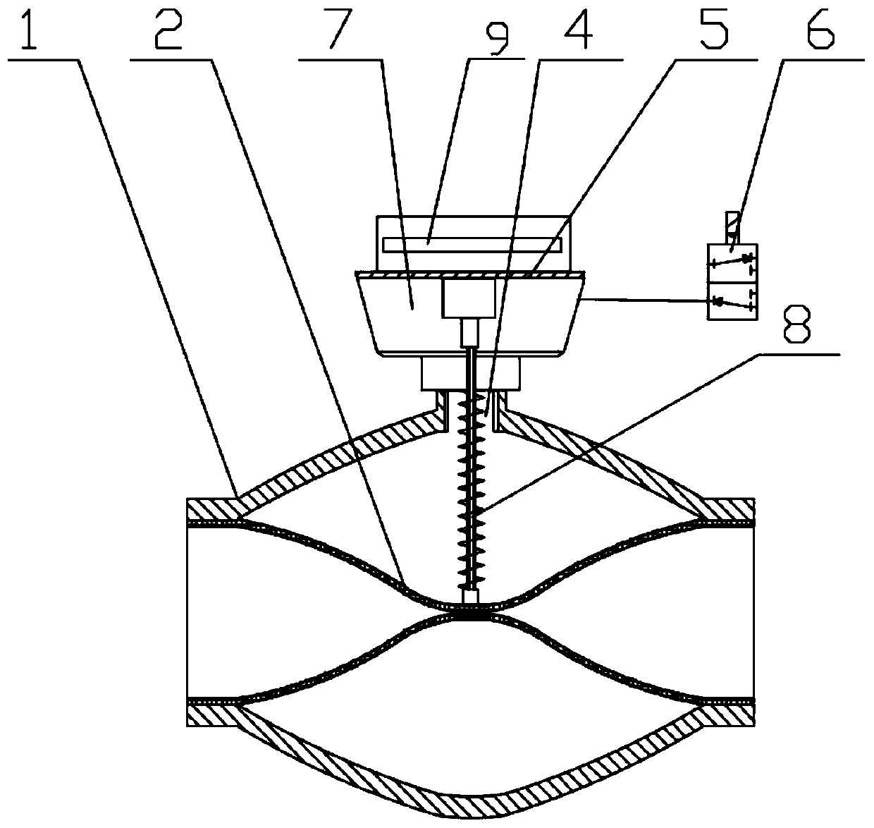
[0047] In this embodiment, the position detection of the hose sleeve 2 in the valve is performed by the spring probe 8. The specific control strategy is shown in the following table:

[0048]

[0049] Compared with the first embodiment, this embodiment adopts the spring probe 8 and the working principle of the capacitance probe 3 is different. Therefore, the fourth detection result in the first embodiment does not exist. The remaining detection results and principles are the same as those in the embodiment. Numbers 1, 2, 3, and 5 in One are the same.

[0050] Compared with the prior art, the present invention can monitor the working status and fault status of the pinch valve in real time and feed it back to the user. The present invention collects the air source status (including solenoid valve power supply voltage and pressure sensor signal) and the radial position signal of the hose sleeve in the valve, and fully considers the possible failures of the pinch valve during operatio...


PUM


Abstract

The invention discloses a pinch valve working state detecting device and a detecting method. The pinch valve working state detecting device comprises a sensor housing, a solenoid valve and a hose sleeve detecting device used for detecting the position of a valve-in hose sleeve. A compressed air interface is formed in a pinch valve, and the sensor housing is connected to the compressed air interface. A pressure sensor diaphragm used for detecting and controlling air pressure is also arranged in the sensor housing. The hose sleeve detecting device is a capacitance feeler lever or a spring feelerlever, and the capacitance feeler lever or the spring feeler lever is inserted into a valve body of the pinch valve through the compressed air interface. The detecting device obtains the corresponding relationship between the air source state and a radial position signal of the valve-in hose sleeve and the working state of the pinch valve by collecting the air source state and the radial positionsignal of the valve-in hose sleeve and giving full consideration to the possible failures of the pinch valve in the operation process, so as to realize the comprehensive monitoring of the working state of the pinch valve.

Description

Technical field [0001] The invention relates to the technical field of pinch valves, in particular to a detection device and a detection method for the working state of a pinch valve. Background technique [0002] The pinch valve is mainly composed of two parts: the valve body shell and the hose sleeve. When the control medium is not input, the cavity between the hose sleeve and the valve body is in communication with the atmosphere, the hose sleeve is in an outward expansion state under fluid pressure and the elasticity of its own material, and the material conveying channel in the hose sleeve opens. When the control medium enters the cavity between the hose sleeve and the valve body, the hose sleeve deforms under the pressure of the control medium, the conveying material passage in the hose sleeve is closed, and the material is blocked. When the pressure is released after the control medium is discharged again, the conveying material channel in the hose sleeve opens again. So...

Claims


Application Information

Patent Timeline
Patent Type & Authority Applications(China)
IPC IPC(8): F16K37/00G01L11/00G01N27/24G01R19/145
CPCF16K37/0025F16K37/005G01L11/00G01N27/24G01R19/145
Inventor 邓崴
Owner 苏州思迪机电有限公司
Why Eureka
Try Eureka