Glow plug and method for the production thereof

A preheating plug and preheating tube technology, applied in combustion methods, lighting and heating equipment, combustion ignition, etc., can solve the problems of using, elastic body can no longer be used as sealing elements, etc., and achieve high heat resistance and reliable cost Effect

Inactive Publication Date: 2013-07-31
ROBERT BOSCH GMBH
View PDF6 Cites 3 Cited by
  • Summary
  • Abstract
  • Description
  • Claims
  • Application Information

AI Technical Summary

Problems solved by technology

In applications where the environment outside the glow plug is no longer cooled, the elastomer can no longer be used as a sealing element

Method used


Image

  • Glow plug and method for the production thereof
  • Glow plug and method for the production thereof

Examples


Embodiment Construction

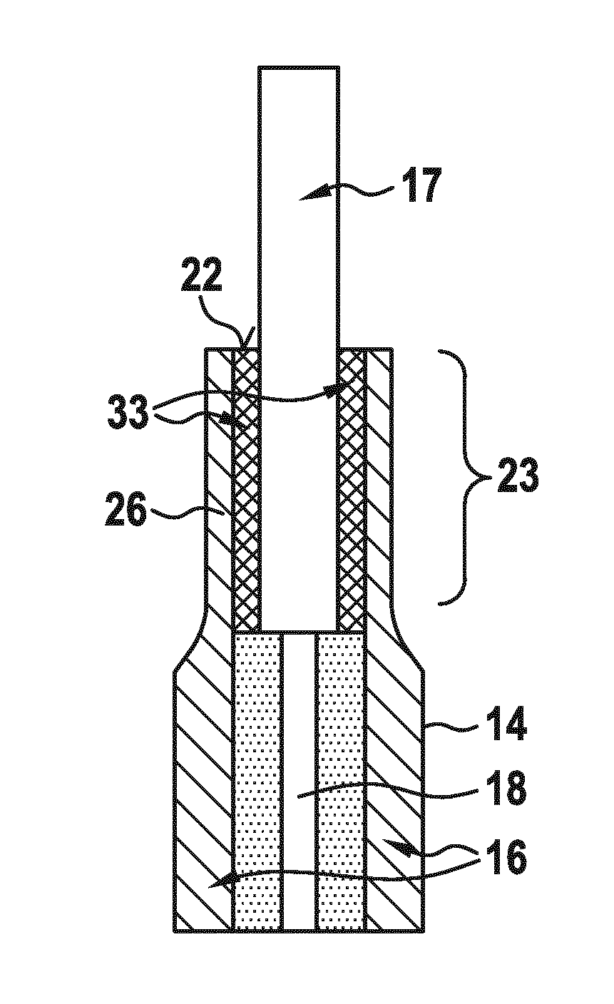
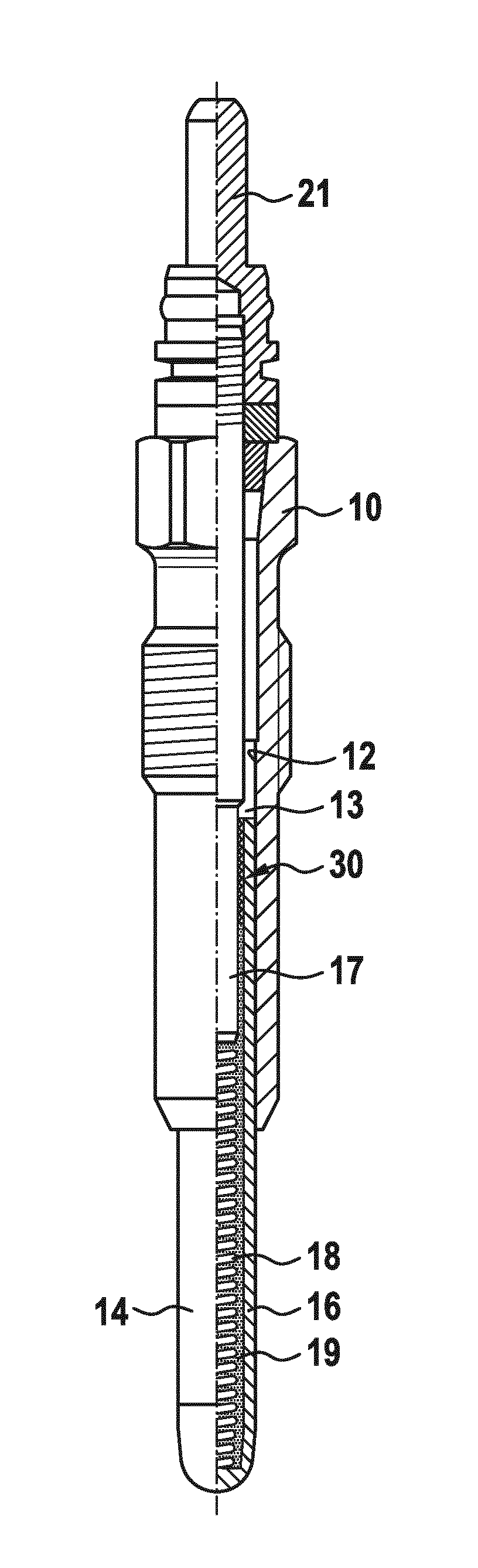
[0011] The glow plug shown in FIG. 1 has a metal housing 10 with a through longitudinal hole 12 into which a glow rod 14 is pressed as a heating body. The glow rod 14 consists of a metallic glow tube 16 in which is arranged a glow plug coil 18 which is in electrical contact with the glow tube 16 at one end and which at the other end is in electrical contact. One end is in electrical contact with the connecting bolt 17 . The connecting bolts 17 leading out of the housing 10 at the end opposite the preheating rod 14 and having the connection 21 are enclosed within the housing 10 by an annular space 13 which is in turn closed to the external environment. of.

[0012] The preheating tube 16 is closed at the end pointing into the combustion chamber of the internal combustion engine and has an opening 22 at the opposite end facing the annular space 13 .

[0013] For the service life of glow plug coil 18 it is important to protect the material of glow plug coil 18 from oxidizing or...


PUM


Abstract

Disclosed is a glow plug comprising a sheathed element (14) which is accommodated in a metallic housing. The sheathed element comprises a glow tube (16) and a coiled element (18) arranged in the glow tube (16), wherein one end of the coiled element is in electrical contact with the glow tube and the other end is in electrical contact with a connecting pin (17). The connecting pin protrudes into an axial opening (22) of the glow tube where the connecting pin is connected in a sealing section (23) to the glow tube in an electrically insulating manner by means of a heating body seal. An electric insulating layer (33) is formed at least in the sealing section on the glow tube and/or the connecting pin. In order to provide a heating body seal, the glow tube is pressed in the region of the electric insulating layer onto the connecting pin.

Description

technical field [0001] The invention relates to a glow plug according to the preamble of claim 1 and to a method for producing the same. Background technique [0002] Glow plugs of the prior art have a glow rod inserted into a metal housing, which is designed with a glow tube and a glow plug coil arranged in the glow tube. The glow plug coil is in electrical contact at one end in the opening of the preheater tube with the connecting screw and at the other end with the metallic preheater tube. The opening of the glow tube is sealed against the external ambient air by means of a heater seal in order to protect the glow plug coil between the glow tube and the connection screw. In order that no short circuit occurs between the preheating tube and the connecting screw, the heater seal is formed by a sealing element made of an elastomer. The maximum temperature for the sealing element made of elastomer is limited to 1000 hours during long-term use at 200°C. Such use restriction...

Claims


Application Information

Patent Timeline
Patent Type & Authority Applications(China)
IPC IPC(8): F23Q7/00
CPCF23Q7/001
Inventor A.赖斯纳
Owner ROBERT BOSCH GMBH
Why Eureka
Try Eureka