Load-control switch and load-control switch system

A load control and switch technology, applied in the direction of electric switches, information technology support systems, telemetry/remote control selection devices, etc., can solve the problem that the main body of the load control switch cannot be replaced freely

Inactive Publication Date: 2013-07-31
PANASONIC INTELLECTUAL PROPERTY MANAGEMENT CO LTD
View PDF23 Cites 1 Cited by
  • Summary
  • Abstract
  • Description
  • Claims
  • Application Information

AI Technical Summary

Problems solved by technology

In the current system, as described in, for example, Matsushita Electric Works, Electrical Equipment Materials Catalog (电容资料カタログ), 2010-2012, page 19, the user can select the color, appearance, etc. of the operating member at a DIY store, etc., However, there is still the trouble that the main body of the load control switch cannot be freely replaced.

Method used


Image

  • Load-control switch and load-control switch system
  • Load-control switch and load-control switch system
  • Load-control switch and load-control switch system

Examples


no. 1 approach

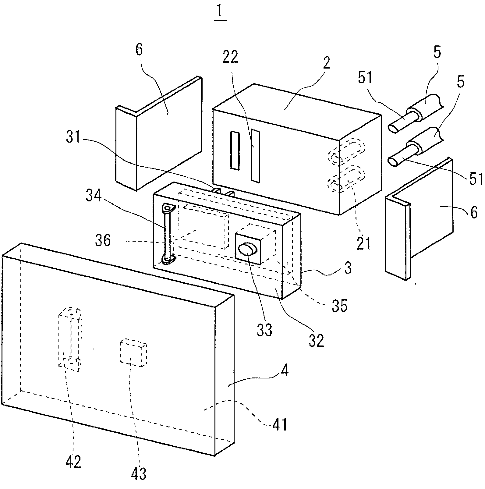
[0041] The load control switch system according to the first embodiment of the present invention will be described. figure 1 It is a figure which shows the basic structure of the load control switch 1 included in the load control switch system of this embodiment. The load control switch 1 includes a terminal block 2 to which an electric wire 5 is connected, an opening and closing function block 3 having a switching function capable of controlling on and off of a load via the electric wire 5 , and an operating member 4 . The terminal module 2 is used to be attached to an installation frame provided on a wall surface of a building. The switching function module 3 is detachably mounted on the terminal module 2 . The operating member 4 is detachably mounted on the opening and closing function module 3 . The electric wire 5 is made of a VVF (Vinyl insulated Vinyl sheathed Flat-type cable: 600V vinyl insulated vinyl sheathed flat-type cable) or the like.

[0042] The terminal mod...

no. 2 approach

[0101] A load control switch system according to a second embodiment of the present invention will be described. Figure 24 It is a figure which shows the structure of the load control switch included in the load control switch system which concerns on this embodiment. In this figure, the same symbols are attached to members having the same configuration as those of the first embodiment described above. Basically, a load control switch 1 consists of a switch module and an operating member. However, in the load control switch system A of the present embodiment, a plurality of load control switches 1 corresponding to a plurality of loads (for example, lighting devices) are simultaneously configured by a plurality of switch modules and one operation member. Figure 24 The following state is shown: the multiple electronic switch modules 8 are directly mounted to the installation frame 9 provided on the wall surface of the building in such a way that the multiple (for example, thr...


PUM


Abstract

A load control switch (1) is provided with a terminal module (2) to which electric wires are connected and which is installed on an installation frame established on a wall surface of a building; and a switch module (3) which is detachably mounted to the terminal module (2) and which turns a load on or off. The load control switch (1) is also provided with an operation handle (4) detachably attached to the switch module (3). The switch module (3) may be an electronic switch or a mechanical switch; an electronic switch may additionally be provided with delay function, timer function, a motion sensor, and so on. This makes it possible for a user to freely replace one load control switch with another having different function without electrical work being required.

Description

technical field [0001] The present invention relates to a load control switch and a load control switch system that can be easily replaced without being qualified as an electrical engineer. Background technique [0002] Among the load control switches installed on the walls of buildings to control the on and off (on and off) of loads such as ventilating fans and lighting devices, other than load control switches that simply perform on / off control, there are known Load control switch for display function, delay function, dimming function, wireless signal receiving function, sensor function, etc. For example, there are cases where it is desired to replace a simple on / off switch with a switch with a dimming function as the switch is replaced with a lighting device, and there are also cases where it is desired to replace the switch of a lighting device such as a hallway with a switch equipped with a human sensor. switch status, etc. In the conventional system, the entire load ...

Claims


Application Information

Patent Timeline
Patent Type & Authority Applications(China)
IPC IPC(8): H01H9/02H04Q9/00
CPCH02G3/10H01H9/54H01H9/02H01H1/5866H01H9/08H01H2300/03Y02B90/20Y04S20/14H04Q9/00
Inventor 东浜弘忠兴梠武志谷利阳子松本一弘长田雅裕植田真介吉木和久
Owner PANASONIC INTELLECTUAL PROPERTY MANAGEMENT CO LTD
Why Eureka
Try Eureka