Full-automatic tube-cutting chamfering machine

A chamfering machine, fully automatic technology, applied in the direction of shearing device, feeding device, positioning device, etc., can solve the problems of end face burrs, slow cutting speed, low cutting precision, etc., achieve absolutely neat cut, low production cost, The effect of low work intensity

Active Publication Date: 2013-08-07
杭州杨氏实业有限公司
View PDF6 Cites 27 Cited by
  • Summary
  • Abstract
  • Description
  • Claims
  • Application Information

AI Technical Summary

Problems solved by technology

[0002]Pipes are used in various manufacturing fields. The equipment for cutting pipes on the market basically saws pipes manually through a pipe sawing machine, and a single cutting saw blade rotates to cut the pipes. Cutting processing, this processing method has low cutting precision, slow cutting speed, high labor intensity of workers, and rough cutting surface, serious burrs are formed on the end face, which will cause serious errors in the positioning of subsequent processing
[0003] At present, there are automatic cutting machines with multiple cutting blades that rotate to cut pipes and perform external chamfering on the pipes. However, this method of rotating multiple cutting blades causes serious and unstable burrs on the inside of the cutting surface, and only the external chamfering is important for subsequent automatic positioning. The error caused is very large, and the internal chamfering also requires subsequent processing steps to remove burrs

Method used


Image

  • Full-automatic tube-cutting chamfering machine
  • Full-automatic tube-cutting chamfering machine

Examples


Embodiment Construction

[0016] The present invention will be described in detail below in conjunction with the accompanying drawings and specific embodiments.

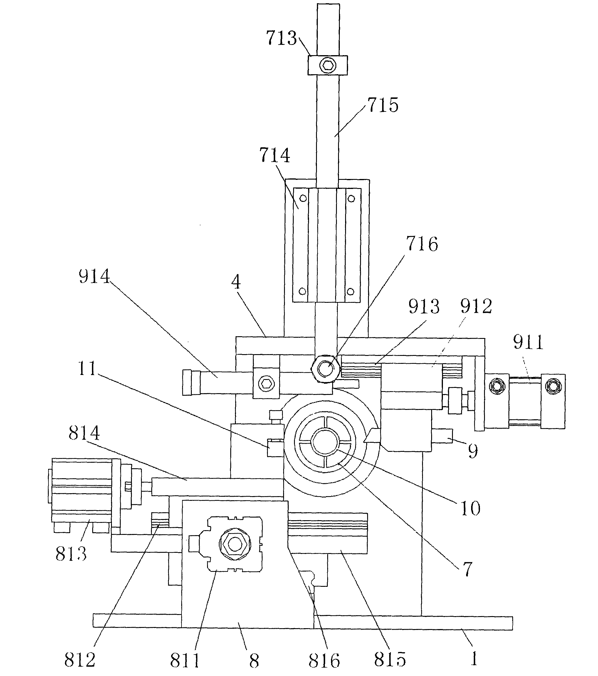
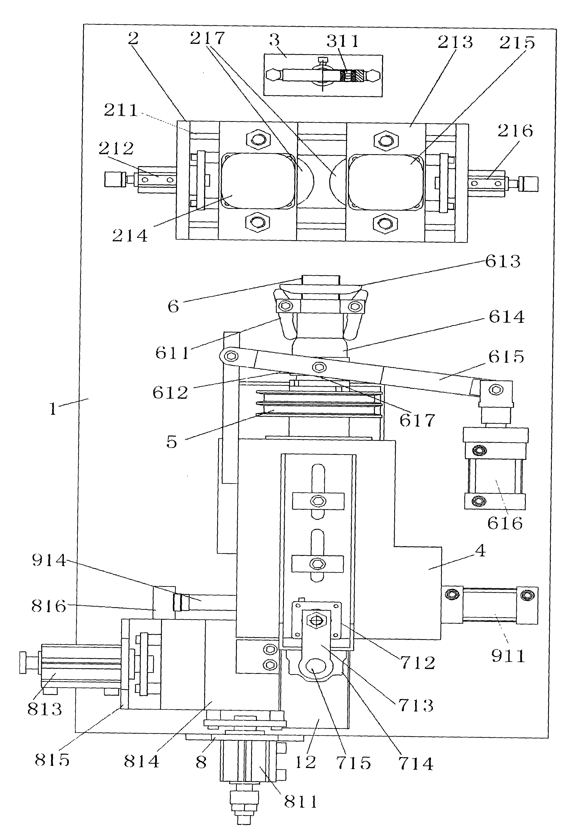
[0017] figure 1 is the view from the discharge end; figure 2 The upper part is the feeding direction, the lower part is the discharging direction, and the discharging direction is the forward direction of the round tube.

[0018] refer to figure 1 , figure 2 , the structure of the automatic pipe cutting and chamfering machine of the present invention is to include a feeding mechanism, a clamping mechanism, a stepping feeding mechanism, a chamfering mechanism and a cutting mechanism which are fixed on the base 1 and arranged in sequence along the feeding direction;

[0019] The feeding mechanism includes a feeding frame 3 and a feeder base 2, the feeding frame 3 is provided with a feeding bearing 311; the feeder base 2 is provided with two sets of symmetrical feeding mechanisms, that is, along both sides of the feeding axis. A pair of fe...


PUM


Abstract

The invention discloses a full-automatic tube-cutting chamfering machine. The full-automatic tube-cutting chamfering machine comprises a feeding mechanism, a clamping mechanism, a stepping feeding mechanism, a chamfering mechanism and a cutting mechanism which are fixed on a base station and sequentially arranged along the material delivering direction. The full-automatic tube-cutting chamfering machine has the advantages that the machine is environmental-friendly; the machine is high in accuracy, performs internal and external chamfering to a cutter edge and then performs length positioning through a cutting surface with no burrs, a round tube rotates at high speed but a cutter does not rotate, and the cuts are absolutely in order; the labor intensity of workers is low, the workers only enable the round tube to penetrate into a spindle in a stand-alone state, and the machine automatically clamps and processes fed materials; the work efficiency is high, one person manages 4-5 machines; the service life of the cutter is long, the adopted cutter is straight and can be grinded, and the cutter can be used again only by being dismantled and repaired after used for a certain times; and the production cost is low, inner circles and excircles can be chamfered in one time, and chamfering processing is not required in the follow-up processes.

Description

technical field [0001] The invention belongs to the technical field of pipe processing equipment and relates to a fully automatic pipe cutting and chamfering machine. Background technique [0002] Pipes are used in various production and manufacturing fields. The equipment for cutting pipes on the market basically uses pipe sawing machines to manually saw pipes, and a single cutting saw blade rotates to cut pipes. This processing method has low cutting accuracy and slow cutting speed. The labor intensity of workers is high, and the cutting surface is rough, and serious burrs are formed on the end surface, which causes serious errors in the positioning of subsequent processing. [0003] At present, there are automatic cutting machines with multiple cutting blades that rotate to cut pipes and perform external chamfering on the pipes. However, this method of rotating multiple cutting blades causes serious and unstable burrs on the inside of the cutting surface, and only the ext...

Claims


Application Information

Patent Timeline
Patent Type & Authority Applications(China)
IPC IPC(8): B23P23/02B23D33/02B21D43/04
Inventor 杨锡其韩杰喻卫刚周宗林韩生玉
Owner 杭州杨氏实业有限公司
Why Eureka
Try Eureka