Rapid punching device for flexible material

A flexible material and punching device technology, which is applied in metal processing and other directions, can solve the problems of untargeted fast punching devices for flexible materials, and achieve the effect of avoiding material adhesion and high punching reliability

Active Publication Date: 2013-08-07
福建新诺机器人自动化有限公司
View PDF10 Cites 5 Cited by
  • Summary
  • Abstract
  • Description
  • Claims
  • Application Information

AI Technical Summary

Problems solved by technology

[0004] The purpose of the present invention is to provide a flexible material rapid punching device to solve the current problem of no rapid punching device for flexible materials

Method used


Image

  • Rapid punching device for flexible material
  • Rapid punching device for flexible material
  • Rapid punching device for flexible material

Examples


specific Embodiment approach 1

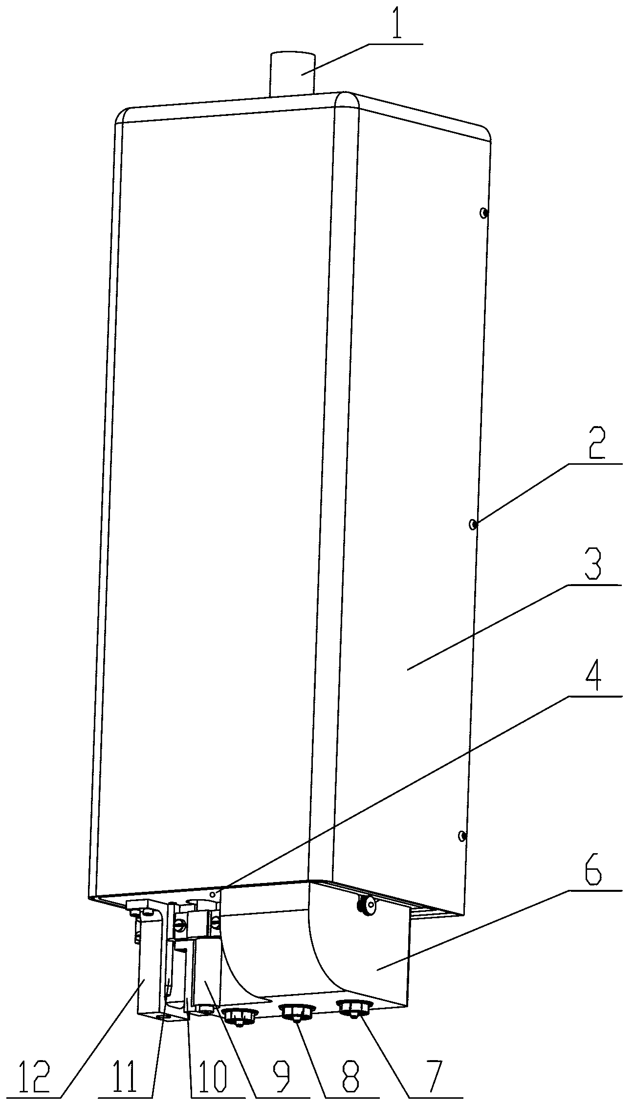
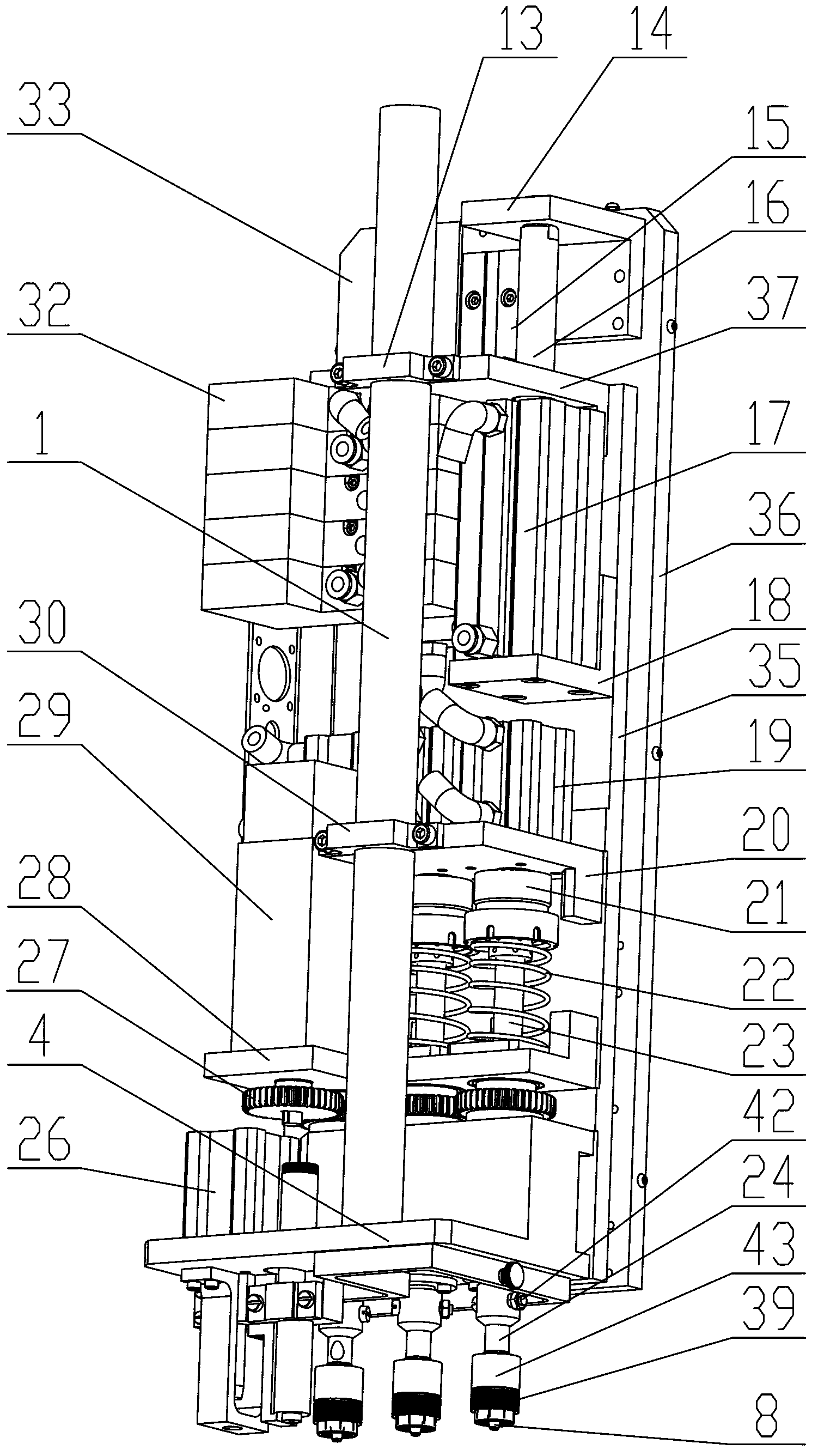
[0009] Specific implementation mode one: combine Figure 1 to Figure 3 Explain, the flexible material rapid punching device of this embodiment, the flexible material rapid punching device includes a front bottom plate 35, a rotary punching knife mechanism and a solenoid valve group 32; the rotary punching knife mechanism includes a cylinder support frame 20. Motor base 28, gear set 27, motor 29, at least one small air cylinder 19 for punching, at least one tool bar connecting sleeve 21, at least one tool bar shaft 23, at least one spring 22 and at least one punching tool head assembly 39 The quantity of small cylinder 19, knife rod connecting sleeve 21, knife rod shaft 23, spring 22 and punching cutter head assembly 39 for punching is all the same, and small cylinder 19 for punching is affixed with front base plate 35 by cylinder support frame 20 , the cylinder rod of the small cylinder 19 for punching is set downwards and fixedly connected with the knife bar connecting sleeve...

specific Embodiment approach 2

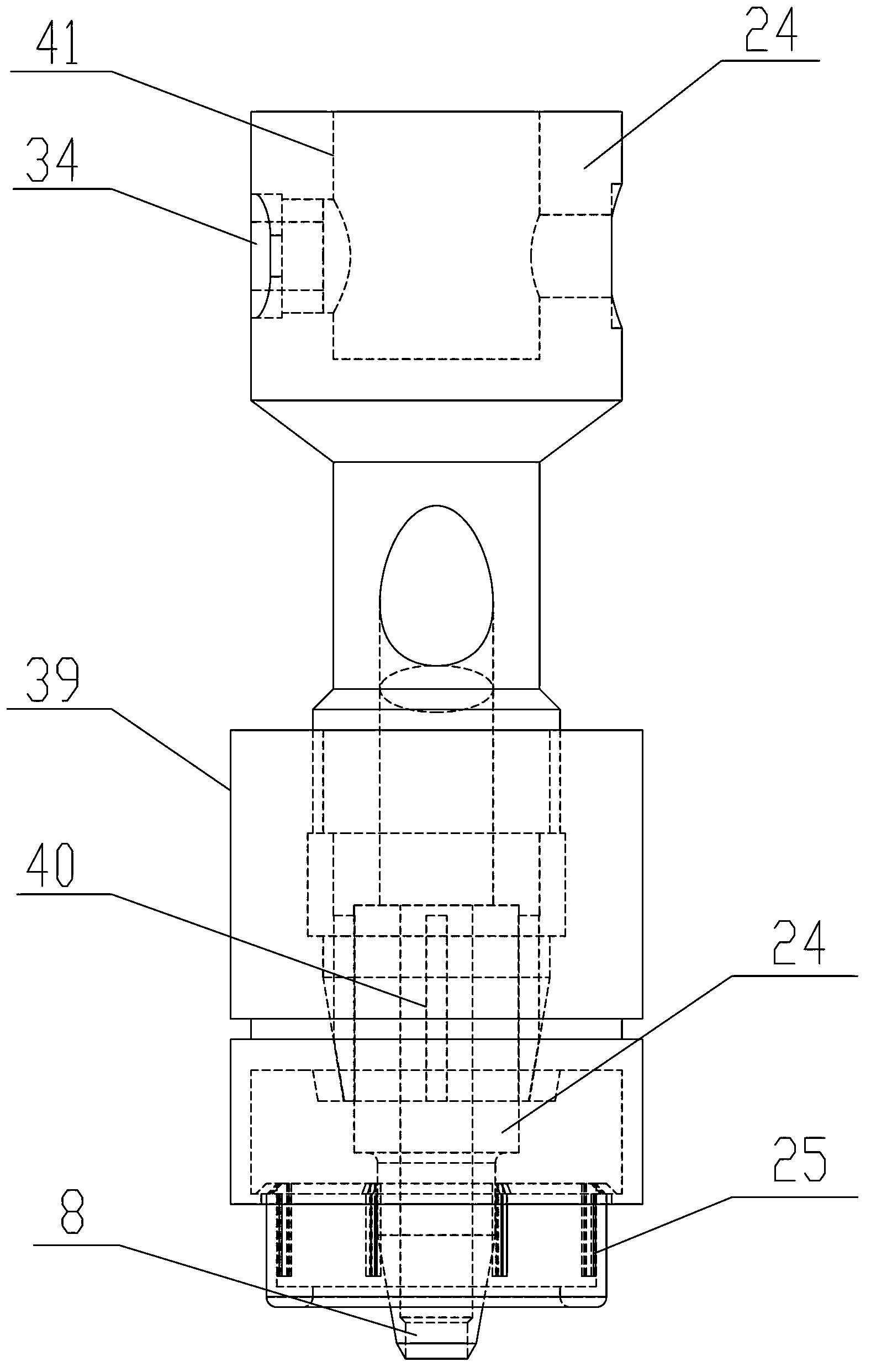
[0010] Specific implementation mode two: combination Figure 1 to Figure 3 Illustrate, the punching cutter head assembly 39 described in the present embodiment comprises punching cutter rod 24, punching cutter rod thread sleeve 34, collet sleeve 25 and punching cutter head 8; The center of the end face is provided with a blind hole 41 axially, the lower end of the tool bar shaft 23 is arranged in the blind hole 41 of the punching knife bar 24, and the side wall corresponding to the punching knife bar 24 and the blind hole 41 is provided with The radial mounting hole, the punching knife bar threaded sleeve 34 is fixed in the radial mounting hole, the punching knife knife bar 24 is fixedly connected with the knife bar shaft 23 by the set screw 42 screwed into the punching knife bar threaded sleeve 34, The punching knife bar 24 and the punching knife cutter head 8 are fixed by the collet cover 25, so that it is convenient to change the punch. The undisclosed technical features i...

specific Embodiment approach 3

[0011] Specific implementation mode three: combination figure 1 and image 3 It is explained that the punching head assembly 39 in this embodiment also includes a punching knife holding ring 7; It is used to reduce the local deformation in the working area of ​​the material during punching. The undisclosed technical features in this embodiment are the same as those in the second embodiment.


PUM


Abstract

The invention relates to a rapid punching device for a flexible material and belongs to the technical field of flexible material punching equipment. The rapid punching device aims at solving the problem that no rapid punching device is available for the flexible material. A punching small cylinder is fixedly connected with a front base plate through a cylinder supporting frame, a cylinder rod of the punching small cylinder is downward and is fixedly connected with a cutter bar connecting sleeve, the upper end of a cutter bar shaft is rotatably connected with the cutter bar connecting sleeve, a spring is sleeved on the cutter bar shaft and is arranged between the cutter bar connecting sleeve and a motor base, the motor base is fixedly connected with the front base plate, the cutter bar shaft is fixedly connected with a gear set, the gear set is fixedly connected with an output shaft of a motor and is driven by the output shaft of the motor to rotate, the motor is fixed on the motor base, a punching cutter head assembly is fixed at the lower end of the cutter bar shaft, and movement of the punching small cylinder is achieved through a solenoid valve for controlling movement of the punching small cylinder in a solenoid valve group. Various pore diameters can be processed rapidly reliably in one time, discharging and lineation can be performed automatically, and accordingly lineation and punching on the flexible materials such as leather and cloth are achieved.

Description

technical field [0001] The invention relates to a flexible material punching device, which belongs to the technical field of flexible material punching equipment. Background technique [0002] On machine tools for processing flexible materials (such as leather, cloth, etc.), it is inevitable to punch flexible materials. Considering the special properties of flexible materials and the number of punching holes is often large, it is necessary to design an efficient , Punching device for flexible materials. [0003] my country is a big country in the manufacture of flexible materials. In recent years, the demand for flexible material manufacturing equipment is very urgent, but domestic research in this area is very limited. For example, there are almost no patents for punching devices for flexible materials (such as leather, cloth, etc.). Patents also cannot provide a good solution. For example, the utility model patent No. 200920071331.9 provides a form of leather punching need...

Claims


Application Information

Patent Timeline
Patent Type & Authority Applications(China)
IPC IPC(8): B26F1/02B26D7/08
Inventor 于福利卢礼华王光男焦徳严
Owner 福建新诺机器人自动化有限公司
Why Eureka
Try Eureka