Locking mechanism, connecting mechanism, connecting assembly and working method of locking mechanism

A technology of locking mechanism and connecting mechanism, which is applied in the layout, transportation and packaging of pedals or ladders, and vehicle components, etc., can solve the problems of increased weight, large vibration inertia, and difficult disassembly and assembly of automatic stepping devices, and can be widely popularized and applied. Meaning, the realization process is simple, the effect of easy maintenance

Active Publication Date: 2013-08-07
ANHUI JIANGHUAI AUTOMOBILE GRP CORP LTD
View PDF5 Cites 3 Cited by
  • Summary
  • Abstract
  • Description
  • Claims
  • Application Information

AI Technical Summary

Problems solved by technology

[0004] The problem of the above-mentioned automatic stepping device is: adopting the universal connector 22, first, the weight of the entire automatic stepping device is increased, the vibration inertia is large during the running of the vehicle, the noise is large and it is easy to be damaged; the second, the cost will be greatly increased; the second Three, not easy to disassemble

Method used


Image

  • Locking mechanism, connecting mechanism, connecting assembly and working method of locking mechanism
  • Locking mechanism, connecting mechanism, connecting assembly and working method of locking mechanism
  • Locking mechanism, connecting mechanism, connecting assembly and working method of locking mechanism

Examples


Embodiment Construction

[0044] Below in conjunction with accompanying drawing and specific embodiment the present invention is described in further detail:

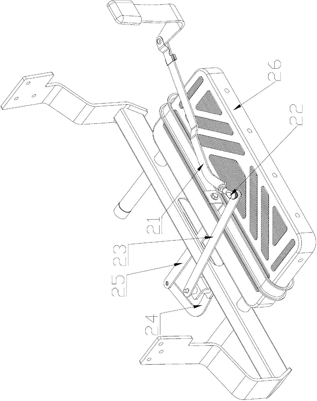
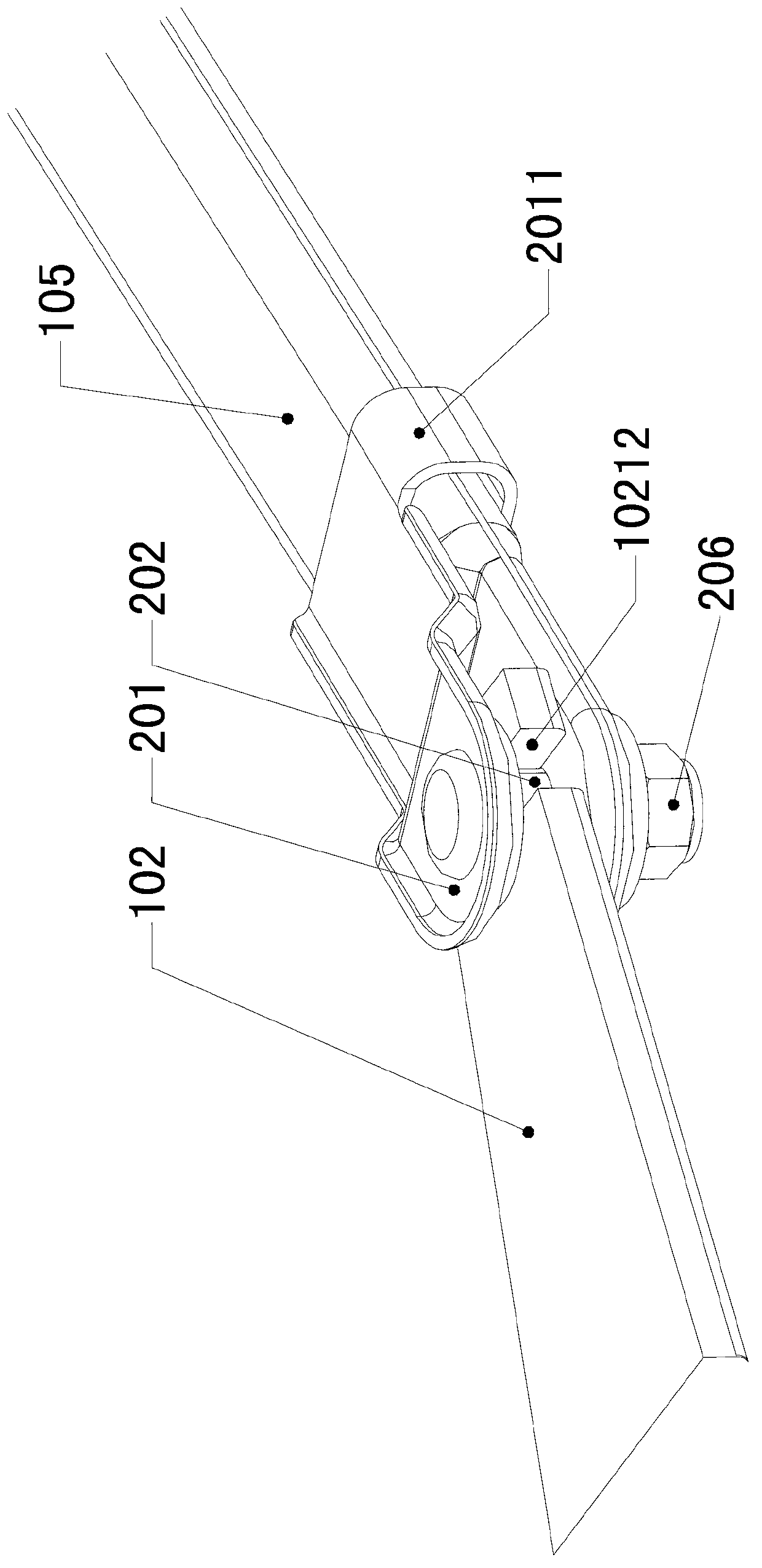
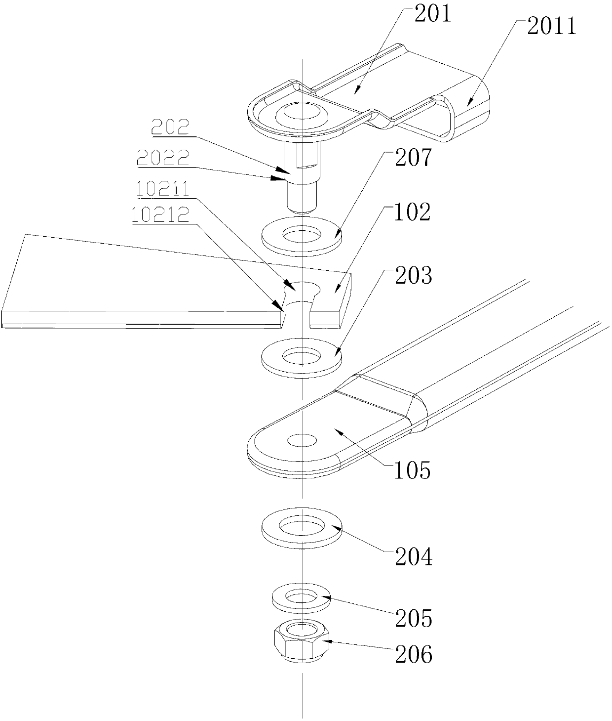
[0045] figure 2 A schematic structural view of the locking mechanism 103 according to the present invention is shown, as figure 2 As shown, the locking mechanism 103 is used to connect the first connection part 102 and the second connection part, and the locking mechanism 103 includes a special-shaped shaft 202 , a first washer 203 and a second washer 204 . specifically:

[0046] Such as Figure 10 with 11 As shown, the second connecting part is a four-bar linkage structure including a first link 105, a second link 107, a third link 109 and a fourth link 108, and the head end of the first link 105 is the first link 105. The head ends of the two connecting parts, and the connecting rods 105, 107, 109, 108 are rotatably connected between each other through pin shafts.

[0047] refer to Figure 3 to Figure 5 , the profiled shaft 202 is sequen...


PUM


Abstract

The invention discloses a locking mechanism, a connecting mechanism, a connecting assembly and a working method of the locking mechanism. The locking mechanism for being connected with a first connection part and a second connection part comprises a special-shaped shaft, a first gasket and a second gasket. The special-shaped shaft is sequentially divided into a first shaft part, a second shaft part and a third shaft part through a flange arranged onan outer wall of the special-shaped shaft along the circumferential direction and the step surface. The tail end of the first connection part and the head end of the second connection part are provided with through holes. The tail end of the first connection part, the first gasket, the head end of the second connection part and the second gasket are in clearance fit with each other and are sequentially sleeved on the second shaft part. A third gasket and a nut are sleeved on the third shaft part, and the third gasket is abutted against the step surface through a nut in threaded fit with the third shaft part . An outer wall of the second shaft part is respectively in clearance fit with an inner wall of the through hole at the tail end of the first connection part, an inner hole wall of the first gasket, an inner wall of the through hole at the head end of the second connection part and an inner hole wall of the second gasket. The first gasket and the second gasket are made of soft wear-resistant materials.

Description

technical field [0001] The invention relates to a connecting device, in particular to a locking mechanism, a connecting mechanism, a connecting assembly and a working method of the locking mechanism. Background technique [0002] The floor of a commercial vehicle is generally higher than 350mm from the ground. In order to facilitate passengers to get on and off the car, an automatic stepping device (telescopic step plate) is generally added to the sliding door. When the sliding door moves backward (door opening process) , The sliding door drives the step board to extend out. When the sliding door is fully opened, the step board is fully extended, and the occupant can get on and off the car conveniently through the automatic step board. [0003] figure 1 A schematic structural view of an automatic stepping device in the prior art is shown, as figure 1 As shown, the automatic stepping device comprises a first connecting part 21, a first connecting rod 23, a second connecting...

Claims


Application Information

Patent Timeline
Patent Type & Authority Applications(China)
IPC IPC(8): B60R3/02
CPCB60R3/02
Inventor 丁光学
Owner ANHUI JIANGHUAI AUTOMOBILE GRP CORP LTD
Why Eureka
Try Eureka