Method for rapidly restraining chaos harmonic waves of coupling generator set

A technology for generator sets and generators, applied in harmonic reduction devices, AC networks to reduce harmonics/ripples, etc., to achieve rapid suppression

Inactive Publication Date: 2013-08-07
王少夫
View PDF0 Cites 0 Cited by
  • Summary
  • Abstract
  • Description
  • Claims
  • Application Information

AI Technical Summary

Benefits of technology

This technology helps prevent chaotic behavior caused by coupling generators used together with other power systems or devices that are connected through wires. It allows us to create an accurate simulation of these systems without having any significant impact on their performance.

Problems solved by technology

This patented describes how chaos can occur when two systems interact with each other during operation due to factors like temperature or pressure changes that affect their behavior. These conditions may cause damage even without causing any problematic effects such as malfunctions or failures within an electric power grid network. To prevent this issue, various techniques aimed at controlling these phenomena were developed over time by scientists working together under specific environmental settings called models.

Method used


Image

  • Method for rapidly restraining chaos harmonic waves of coupling generator set
  • Method for rapidly restraining chaos harmonic waves of coupling generator set
  • Method for rapidly restraining chaos harmonic waves of coupling generator set

Examples


Embodiment Construction

[0024] The coupled generator system is composed of two generators placed together, the two are coupled to each other, and the system coupling equation is:

[0025] , , , (1)

[0026] in and , and are the rotation angular velocity and current of the two generators, respectively, and is the torque of the generator rotor, are the loss effect factors greater than zero, transforming equation (1), we can get:

[0027] (2)

[0028] in, are the three control parameters of system (2), where is a positive parameter, is a non-zero parameter, , The smaller the value, the greater the mechanical damping loss, so the loss-coupled generator model established by the present invention is more universal to reflect the actual engineering situation.

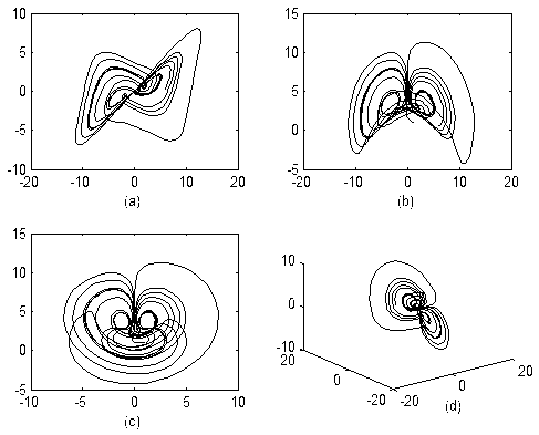
[0029] 1 Phase trajectory and chaotic attractors of the system

[0030] The system has five equilibr...


PUM


Abstract

The invention discloses a method for rapidly restraining chaos harmonic waves of a coupling generator set. The method includes indicating mutual actions of current, inter parameters and electromagnetic fields in a generator set system with a three-dimensional nonlinear equation as complicated nonlinear behaviors exist in the coupling generator set system, and discovering harmful chaos phenomenon in the coupling generator set under certain conditions through analysis of aspects of a phase track diagram, a bifurcation diagram, maximum Lyapunov index and Pioncare mapping and the like. Finally, the method which is easy and simple, can rapidly restrain the chaos phenomenon of the coupling generator set system, and accordingly has certain values to practical electrometrical control.

Description


Claims


Application Information

Patent Timeline
Owner 王少夫
Why Eureka
Try Eureka