Sub-circuit extracting method of digital logic circuit

A technology of digital logic circuit and extraction method, applied in the direction of logic circuit with logic function, etc., can solve the problem of no common part, etc., and achieve the effect of strong versatility

Active Publication Date: 2013-08-07
NINGBO UNIV
View PDF0 Cites 16 Cited by
  • Summary
  • Abstract
  • Description
  • Claims
  • Application Information

AI Technical Summary

Problems solved by technology

(1) f 1 completely belongs to f; (2) f 1 Only ...

Method used


Image

  • Sub-circuit extracting method of digital logic circuit
  • Sub-circuit extracting method of digital logic circuit
  • Sub-circuit extracting method of digital logic circuit

Examples


Embodiment

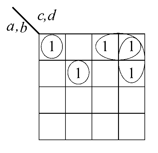
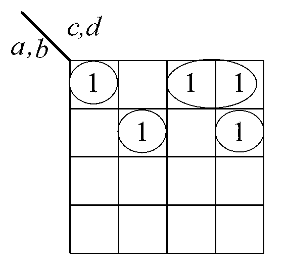
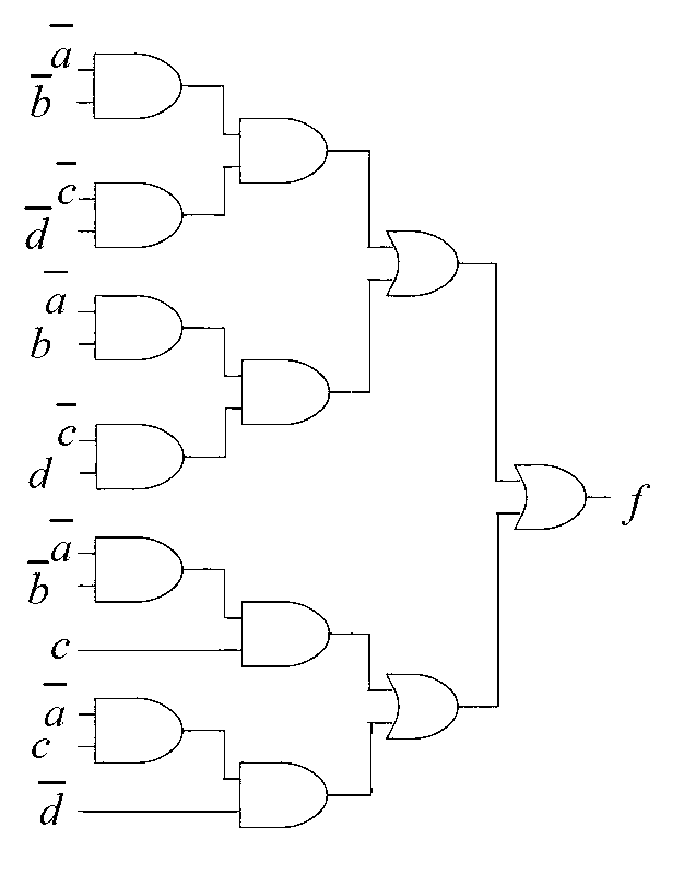
[0038] A sub-circuit extraction method of a digital logic circuit is characterized in that the logic function corresponding to the original circuit is defined as f, and f is expressed as a logic "or" form of m product items; the logic function corresponding to the sub-circuit is f 1 , f 1 Expressed as a logical "or" form of n product items; the set of product items corresponding to f is C, f 1 The corresponding set of product terms is C 1 ;C contains m product terms, any one of which is defined as p i ;C 1 contains n product terms, any one of which is defined as p k ; Symbol "Θ" represents the disjoint sharp product of two known Boolean logic function product terms; does not appear in the product term; and assume that the logic function corresponding to the original circuit is a single-output logic function The bit corresponding to the subcircuit that needs to be extracted is a single output logic function f 1 =a, then C={0-00,1--1,1-1-}, C 1 ={1---}, m=3, n=1; the spe...


PUM


Abstract

The invention discloses a sub-circuit extracting method of a digital logic circuit. By the aid of disjoint sharp-operations between logic function product terms, the product term set belonging to the logic functions corresponding to the sub circuits is eliminated from the product term set of the logic functions corresponding to original circuits, so that sub-circuit extraction from the original circuits is realized. A novel circuit construction method with sub circuits is further provided to be equivalent to logic functions of the original circuits.

Description

technical field [0001] The invention relates to a method for optimizing a digital logic circuit, in particular to a method for extracting a sub-circuit of a digital logic circuit. Background technique [0002] On the premise of keeping the function of the digital logic circuit unchanged, how to reduce the area of ​​the circuit, that is, optimize the area of ​​the circuit, has always been an important goal of the logic synthesis and optimization of the digital circuit. In digital circuit logic optimization, in order to realize circuit area optimization, it is often necessary to separate some parts of the original circuit as sub-circuits from the original circuit and extract them to achieve the purpose of circuit simplification. [0003] Assume that the expression of the logic function f corresponding to a digital circuit is: [0004] f ( a , b , c , d ...

Claims


Application Information

Patent Timeline
IPC IPC(8): H03K19/20
Inventor 王伦耀夏银水储著飞
Owner NINGBO UNIV
Why Eureka
Try Eureka